U nás se prodává poměrně dost anténních přepínačů. Popravdě řečeno – nesháněl jsem se po nich. Až do jedné chvíle.
Můj prvotní zájem o přepínače vyprovokoval QSL lístek od operátora z Argentiny, který měl v pozadí nad pracovním stolem tenhle typ, s nímž jsem se zatím osobně nesetkal, přestože navštěvuji dost často různé burzy nebo radioamatérská setkání jako Holice atd. Musím podotknout, že k výrobě tohoto anténního přepínače mě přiměl až jeho e-mail, ve kterém mi napsal veškeré parametry. Načež další řádek obsahoval dotaz, jestli ho nechci poslat za pouhých $50. Vzhledem k tomu, že zrovna u nás byl kurs k dolaru přes 40,- korun jsem naznal, že pro mě je to trochu moc. Takže proč si ho vlastně neudělat, že?
 |
 |
Protože jsem věděl co chci (dle obrázku), byl jsem vlastně limitován jen vhodným přepínačem. Volba padla na přepínač z vyřazené vojenské techniky. Byl to 11-ti polohový přepínač na keramické destičce. Bylo zapotřebí odstranit každý druhý kontakt, aby přepínač měl 5 poloh a výstup. Opatrně jsem odvrtal nýtky, které držely tyto kontakty, ale to byla ta nejmenší práce.
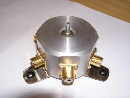
Následovalo nakreslení výkresu, podle kterého se posléze vysoustružilo a ofrézovalo tělo celého přepínače. Jako bývalému strojaři mi tohle větších problémů nečinilo a za jeden večer byl výkres hotov. Materiál jsem měl a pokud bych měl patřičné nástroje doma, tak bych si to vytočil a opracoval sám. Ale bohužel.
 |
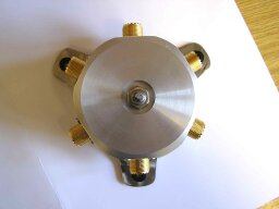 |
Je dnes sice jiná doba, ale i tak se dá ledacos zařídit. A tak jsem nelenil, vzal výkres a navštívil pár známých, kteří se tohoto úkolu zhostili nanejvýš dobře. A nebylo to poprvé. Za to jim patří můj dík. Bylo potřeba jen pár korekcí ve výkresech, aby se dopilovaly drobné nedostatky – a skelet byl na světě.
Další problém nastal, když jsem začal shánět PL konektory s teflonem. Je to skutečně nedostatkové zboží. Ale nakonec se podařilo.
 |
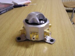 |
Po našroubování konektorů na skelet jsem pokračoval v úpravě přepínače. Ta spočívala v jeho úplném rozebrání a sejmutí aretačního kolečka z osy přepínače, které určuje polohu přepínače. Samozřejmě, že jsem jej mohl nechat v původním provedení, ale nač přepínat o jednu polohu navíc, která nebude stejně zapojená, když nemusím. Sehnal jsem kousek asi 1,5 mm silného nerez plechu a začal jsem pilovat nové polohy s tím, že každou druhou jsem vynechal. Dále bylo zapotřebí se trefit s otvorem na osu přepínače, neb ta je obdélníková, a pokud se minete v natočení, nebude vám sedět poloha po sešroubování celého přepínače dohromady a jako takový nebude funkční. Podařilo se napoprvé. Jediné, co se muselo udělat, bylo to, že se aretační kolečko přivařilo CO2 a povrchově jsem jej nechal upravit pochromováním. Původní bylo nalisováno a lepší řešení jsem nenašel. Zadní strana je uzavřena víčkem s šesti šroubky, na který je přidělán držák.
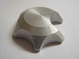
Přemýšlel jsem, jaký bych mohl použít knoflík na přepínání. Bohužel nabídka nějakých slušných knoflíku u nás není a tak volba padla na vlastní návrh, který opět zrealizovali dle výkresu moji známí.
 |
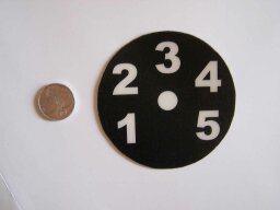 |
Přepokládal jsem použití přepínače jak na jednom místě, tak možnost použití na portaiblu. Výsledkem byl podstavec ze zbytku nerezového plechu, na kterém přepínač pěkně drží při přepínání antén na stole (díky gumovým průchodkám), nebo za který se dá přišroubovat na zeď.
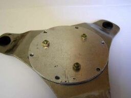 |
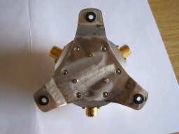 |
Na závěr stačilo ještě označit anténní vstupy čísly 1 – 6 za použití samolepících oboustranných izolep a samolepící průhledné fólie, kterou jsem přelepil z laserové tiskárny vytištěný štítek.
A výsledek vcelku stojí za to. Posuďte sami.
Vlado
Tu by článok mohol končiť. Vlado sa však na mňa obrátil s otázkou na maximálny možný výkon, ktorý takýto prepínač znesie, no nevedel som mu zodpovedne odpovedať, tak som poprosil o pomoc Honzu OK2BNG:
Viliam,
srdečně Tě zdravím z Klimkovic.
Tyto přepínače důvěrně znám. Byly použité v PA typu ZZ 1002,1003,1004, kde je lampa GU74b s Pout cca 800 W.
Myslím si, že mohou přenášet výkon na KV okolo „One kW“ za určitých podmínek:
- přepínač se musí přepínat BEZ zatížení, jinak uhoří péra
- na anténě nesmí být velká jalová složka, max do xj cca 20, jinak dojde k přeskoku na zemnicí šroubek, pokud je zrovna tam zapojená takováto anténa
- pro ilustraci připojují několik foto podobných přepínačů, ale pokud máš CD PA1, tak tam ty foto najdeš
- podobné přepínače antén jsem používal i pro kontesty, ale to vždycky vyhořelo, protože operatoři v zápalu boje přepínají i když mají sepnutou šlapku. Proto jsem to nakonec řešil s relátky typu R 700, kde paralelně spojené s kontakty pohodlně přenesou na KV i 3 KW. Přepínání antén v pauze, kdy není aktivní žádný PA, je někdy oříšek, ale není to neřešitelné. Ale to je již jiné téma.
 |
 |
Nakonec z obecné VF techniky platí, že přechodový odpor je plocha x tlak. Pak se lehce může stát, že je velká i postříbřená plocha, ale tlak tam není. Na druhé straně vidím v PA 2 kW malé přepínače, kde je na pérech obrovský tlak. Pak je plocha minimalizovaná.
Někdy dávno jsem dělal výzkum na takových kontaktech zjednodušeným způsobem. Přeženeš přes to VF cca 10 MHz s proudem cca 6A a měříš úbytek napětí osciloskopem. Tak jsem porovnával různá vakuové relátka a tyto spínače.
Myslím, nemohu to momentálně najít, že v jednom ruském Spravočniku uváděli na tyto přepínače proud okolo 3A trvale. Když vezmem v úvahu nějaké to „káčko“ provozu, tak vyjde těch 5 A , což je při 75 ohmech cca 1875 W na reálné zátěži. A protože reálná zátěž je utopie, tak těch 1250 W určitě to přenese za vyše stanovených podmínek.
Vše dobré přeje
Honza , OK2BNG
Chcem sa poďakovať obom – Vladovi za vynikajúci článok aj Honzovi za technické údaje. TNX! OM0AAO, Viliam
