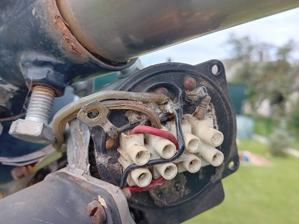
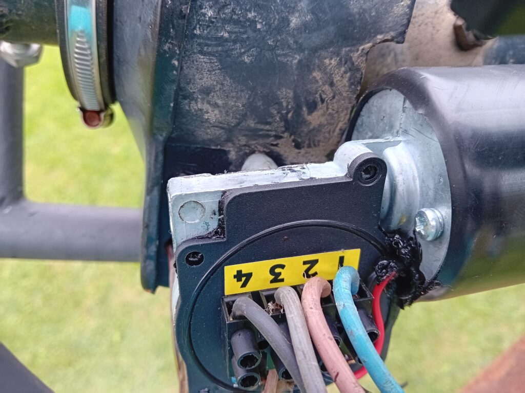
After successful repair of AlfaSPID rotator to RDM-12 towers - after replacing the motor unit - I encountered a feature in operation that did not suit me. Despite the fact that the Rot1prog controller had a connector on the rear panel for PC connection, the controller did not communicate with the computer.
After consulting with Jacek from AlfaSPID, we found that this version of Rot1prog controller does not yet have a PC connection in the firmware. Since it was an older version, the only option was to purchase a new controller. It went out 220 € plus postage. This is a considerable amount. I thought about using the presets, where one click could be rotated by a rotator in the default direction and then picked manually. However, the speed of filming did not suit me. This can be increased by using a higher power voltage for the engine. There were several reasons for which I started looking for the possibility of building a new controller for the Alfaspid rotator.
You will find in the article
Method of reading the position of AlfaSPID rotator
AlfaSPID rotator uses pulses to determine the position. The principle is that during calibration, the rotator is set to the basic azimuth. The rotation from it is then detected number of pulses (for example, 40° from the base azimuth will be 40 pulses). After rotation, the rotator saves the new position to EEPROM memory.
There are not many controllers that support this method. I found connections RA0SMS, K3NG with Arduino MEGA and a series of SP5GNI controllers. After considering and comparing the designs, I decided to go with Mirko's version, SP5GNI.
Connection of controller to AlfaSPID rotator SP5GNI
The connection is very clear. The circuit with resistor R1 and optocoupler OK1 ensures the detection of pulses from the rotator. The 74LVC1G17DBV circuit shapes them. This signal is fed to the input Arduino Nano. Its other inputs are a set of four buttons (only three are used): right, left, and STOP.
On Arduino Nano via I2C bus connected double-row LCD display. Two power relays control the polarity of the voltage supplied to the rotator motor. This voltage is provided by a separate 12 to 24V power source exclusively for powering the power section. The indication is complemented by a pair of LED diodes.
The power supply of the logic part is from +5V supplied to the Arduino. A regular charger or computer can be connected to this connector. This then enables control by software such as DXView, HRD, N1MM Rotor, PstRotator, and similar.
Design of controller for AlfaSPID rotator SP5GNI
SP5GNI placed the documentation and necessary code on his GitHUBhttps://GitHUB.com/sp5gni/GNI-r3-rotator-controller For programming Arduino, the LiquidCrystal_I2C library (SP5GNI), which is available at https://hf5l.pl/wp-content/uploads/2021/04/LiquidCrystal_I2C.zip I am warning you in advance because other LiquidCrystal_I2C libraries did not work with this code.
I first tried the connection on a universal PCB. The controller responded to the rotation command, but the program did not display azimuth. Only by intercepting the data sent to and from the PC did I realize that the packet with data from the controller is incomplete and one byte is missing. At that time, I was already discussing the issue with Miroslaw via email, and practically at the same time, we came up with both the problem and its solution.
After this correction, the driver worked exactly as expected. GitHUB placed an updated version that fixes the error.
Relay module
Output from Arduina I connected to 2-channel relay module. These modules provide a galvanic department and you will not buy the relay itself for a price of over € 2. Display 1602 with i2C,Arduino Nano,2-channel relay module to GX16-4 connectors i bought through eshop https://techfun.sk
Power supply for rotator motor
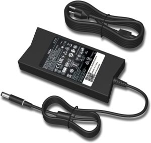
The power supply for the engine provides a source for a notebook 19V/6.7A DA130PE1-00 ADP-1330DB. However, other models that fit voltage and current can also be used. Such power supplies can be relatively inexpensive to get the second hand, for example, through Bazoš
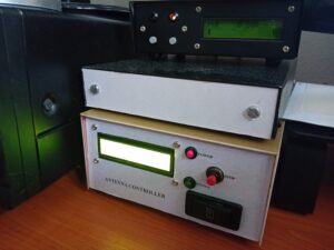
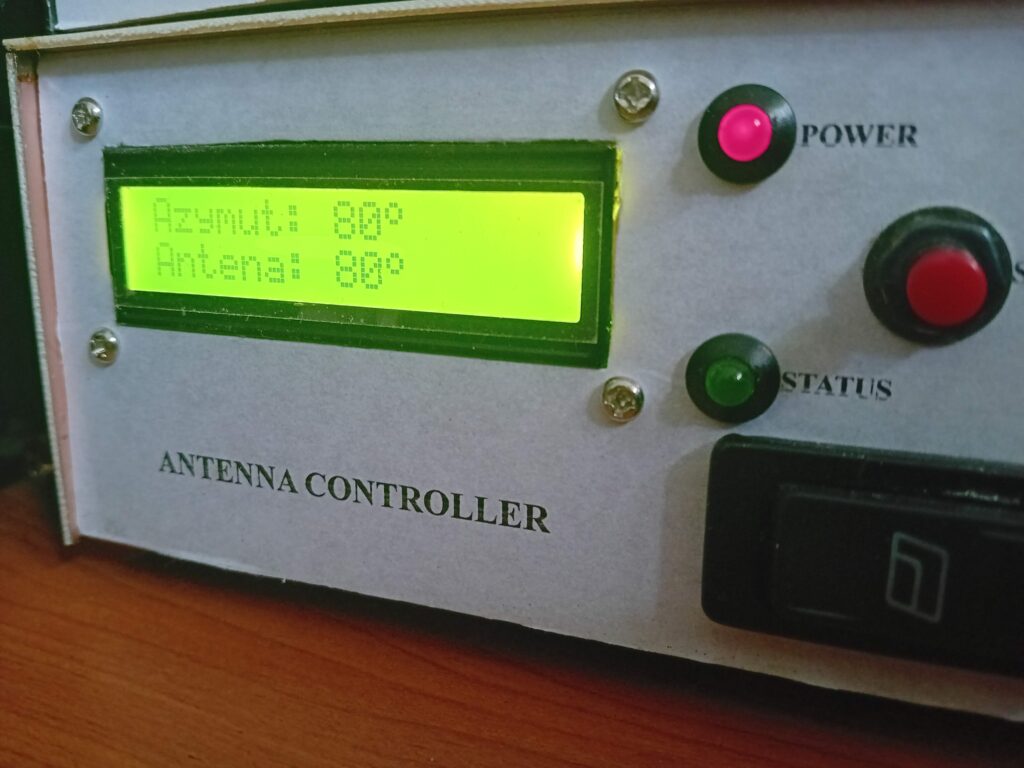
The construction is in the cabinet of Kuprextit. To control the right - I used the switch to the left. It is simple and understandable, and it eliminates unwanted pressing of both buttons at once.
Evaluation after several months of operation
The SP5GNi controller works well. The cost is approx. 50 €, which is a fifth of the price of the original Alfaspid controller. There is also a link to a PC link to the Pstotator:

Also, I am somewhat time with Jackem Rot1prog error, any after the command sent from the PC to the freezing of the towel control. The only one was to buy a new check -up… Finally, I am a mistake we found the work -we found in addition to the stop button, which will unlock the CW/CCW buttons. And another mistake is so -called. "208", when it is default set azimuth to which it revolves in the way, when the "cure" controller from the PC. But even for this, Immil Workaround helps Hamlib, which I use.
Postscript
Did a version of Rot1Prog really exist that did not have RS232 or USB?
I bought the rotator with a tower with RDM-12 after SK. The tooth of time was noticeable, but it looked like it would be 'ready to use'. How wrong I was...
... but the fact that it doesn't have a connection to PC was a surprise, because the cable is connected to the controller. For a few evenings I was trying to figure out if I had an error in the cable to PC, if I had incorrectly configured software, if...