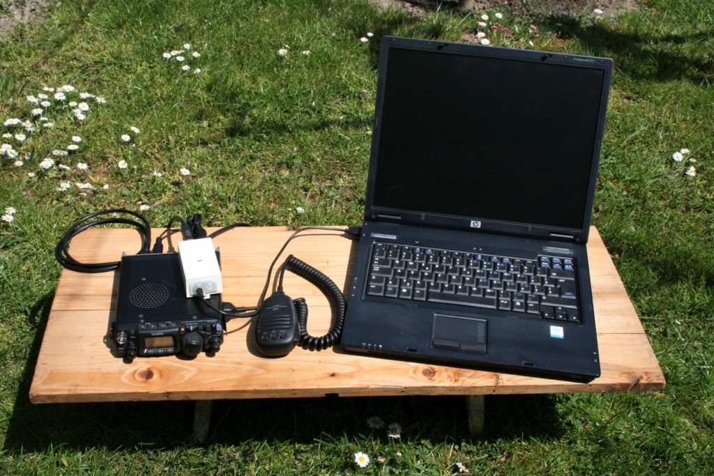
In the previous article I described the interface for transceiver Kenwood TS-870S, which added another mode to our HAM family. I must say that in my sister, OM1ADA, it sparked an unprecedented passion for digi, especially FT8 a FT4, which is also evidenced by her Article where she described her personal impressions and experiences from live operation. Her collection of FT8 diplomas is growing merrily and currently has issued over 500 pieces. With this article, I want to encourage other operators who have not yet decided to venture into the new waters of our fascinating hobby. With little effort, we will get a lot of joy. After all, today the construction of our own digi interface is really undemanding and accessible. Yes, the connection works reliably, but over time the need for an interface for a TCVR from a different manufacturer arose because each brand provides a different solution.In her HAM arsenal, there are still Yeasu FT-817ND and FT-100D radios. The difference is already apparent compared to the TS-870S in that they have a completely different type of ACC2 connector and different levels of audio signals. The advantage of Yeasu lies in the possibility Push to Talk through the CAT interface, which I will detail later. In addition, there was an attempt to completely avoid the RS232 converter. Enjoy reading.
You will read in the article
Construction
The main idea is to save as many computer ports as possible. Today's manufacturers of computer technology only build USB interfaces and, as is usually the case on the user's side, they occupy themselves with other devices and we don't even notice how. The interface requires only one USB port, but as is known, three ports are usually needed for digi operation: one for sound signal (input and output), PTT, and for greater convenience, a CAT interface for controlling the TCVR from a computer. This dilemma is easily solved by USB, which branches one USB port into several. Several radio amateurs have already come up with this idea. For example Dan, The solution of which was developed by John., whose solution was developed by John, to a truly impressive form. The connection is intended for the TCVR Yeasu FT-817ND, but there should be no problem with another model of the same manufacturer, which has a built-in ACC2 and DATA connector, for example, FT-100D. into a really impressive form. The connection is intended for TCVR Yeasu type FT-817ND, but there should be no problem with another model of the same manufacturer that has a built-in ACC2 and DATA connector, for example FT-100D.
Bill of materials
I attach images of components with descriptions for easier sourcing. The total costs are around 15 €.
CAT USB cable
Detailed description: FTDI FT232RL USB Cat & Programming Cable for Yaesu FT-100 FT-817 FT-857FT-897 CT-62 equivalent on Technofix
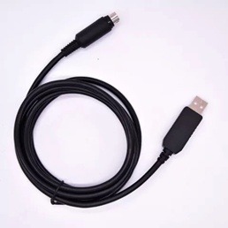
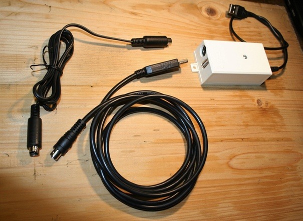
The cable at the other end contains an 8-pin mini DIN connector for the ACC2 port. It represents one of the more expensive parts around 10 €. Its advantage is that you no longer need to make the cable. In the connection, it serves two purposes. The first for controlling the TCVR, for example, for comfortable band tuning and the second for PTT.
6-pin mini DIN Data connector
Detailed description: 10pcs/lot 6 Pin Mini DIN Male Plug Wire Connector W/ Plastic Handle Mini DIN Adapter Converter for Keyboard/Mouse DIY
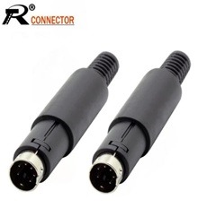
It is connected to the TCVR DATA connector. A connector well known to some for the PS/2 port, which was used to connect a mouse or keyboard to the computer. I decided to make the whole cable. But whoever wants can solder one end directly to the board and save another connector. It depends on the current conditions. A package of 10 pieces will cost around 6 €.
USB Hub
Model 4 Port USB Hub 2.0 Multi USB Splitter Hub Use Power a d a pter Multiple Exp a nder 2.0 USB Hub For Desktop L a ptop PC
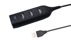
It forms the backbone of the entire interface. It connects its active parts. It ensures communication through the ports. It is the reason why now one USB port on the computer is enough. Basically, any model can be used. The price ranges up to 1.5 €.
USB sound card
Model Mic Spe a ker a udio Interf a ce For L a ptop PC Micro D a t a Bl a ck 3D USB Sound C a rd USB a udio 5.1 Extern a l USB Sound C a rd a udio a d a pter
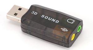
Price around 1 €.
Resistors
- R1 100 Ω
- R2 3k3 Ω
- R3 1k2 Ω
Any power and size, whatever the drawer yields.
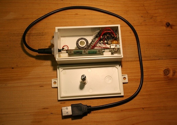
Of course, there are also such necessities as a box or cables, but everyone will choose them according to their conditions and preferences. And they will also adjust the dimensions of the box. Mine is from a distribution box and is generous in space. The individual parts fit in with room to spare.
Circuit diagram
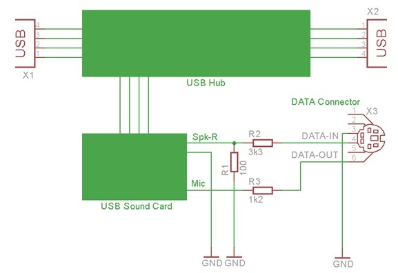
The difference compared tosolution Y03GGX lies in the fact that there is no PTT circuit here, as I use PTT via CAT.
USB hub is connected with a USB sound card (USB Sound Card) via cables as if it were through a USB connector. The cables connect the outputs via jack connectors right speaker output (Spk-R) and microphone input (Mic) through matching resistors R1 and R2 with the data input TCVC and through resistor R3 with the data output TCVR. The numbering and function of the DATA connector pins are clear when looking at Figure 1 and Figure 2.
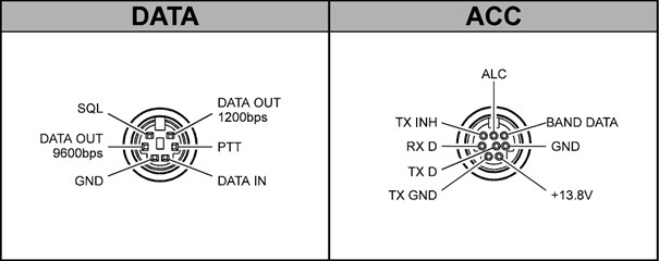
Those who would like to control PTT via optocoupler can use the second USB port. Then a USB to TTL level serial communication converter will be necessary. More details in the mentioned solution from YO3GGX.
Device construction process
Prepare the framework of the interface first. Carefully 'expose' the USB Hub and remove excess USB connectors. If you want to use the remaining ports for their original purpose, you can leave them, but I removed them to minimize the dimensions of the box. Carefully remove the cover from the USB sound card, detach the USB and jack audio connectors. Use the free leads from the USB connector to connect the USB hub and USB sound card. Solder wires to the holes where the jack connectors were and add resistors according to the schematic. Note: I connect the Mic output through R3 to DATA OUT.1200bps. I tested the connection 'exposed' because it will be securely attached to the box. No screwing. The boards are glued with a chemical pen, but epoxy or silicone adhesive can also be used.
Setting up the TCVR FT-817ND
To properly function the interface, it is still necessary to set on TCVR:
- Fashion: DIGI
- Menu #26 - DIG MODE: USER-U
- Menu #51 - VOX GAIN: 1
I left the other settings unchanged.
Setting up software for digital modes
In this section, I will describe the process of setting up the software equipment for digi operation. I use Windows 10 operating system. First, we connect the TCVR to the interface and the interface to the computer. The driver installation should start automatically. Then we make sure that the drivers have been installed correctly. We press the key combination Win + R, we write devmgmt.msc and press Enter. The device manager (Device Manager) will open. Sub Ports (COM & LPT) we find the port number that the system assigned to our CAT interface (green box). In my case it is COM6. We will also check the sound card device. We should find it under Sound, video a nd g a me controllers (red box). My device is called USB PnP Sound Device. Note the port number and the name of the audio device (Figure 3). It is advisable to turn off power saving in the port settings. Otherwise, communication will "freeze" after a while.
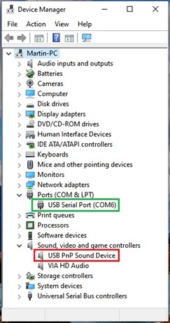
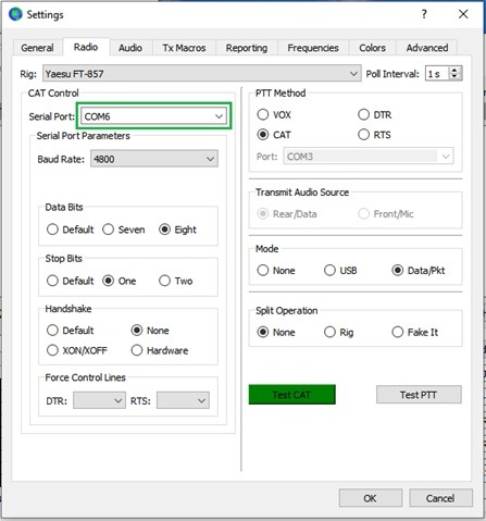
The following is a description of the program settings WSJT-x v2.2.2 for FT4 or FT8 operation. First, we set TCVR by opening the File à Setting menu and going to the Radio tab. First of all, we choose Yeasu FT-857 as Rig (FT-817ND was not in the menu and the FT-817 option did not work for some unknown reason). We go to the CAT Control section and for Serial Port we choose the port number found from the device manager (Figure 3).
We choose Serial Port Parameters as follows:
- Baud Rate: 4800
- Data Bits: Eight
- Stop Bits:
SheTwo (updated) - Handshake: NShe
- Force Control Lines: None
I have the other parameters set as follows:
- PTT Method: C a T
- Fashion: Data/Points
- Split Operation: NShe
We verify the correctness of the settings by pressing the buttons CAT test and subsequently PTT test. Both should be green. Confirm the set option with the OK button (Figure 4).
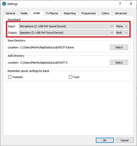
Let's go to the next Audio tab. Here we choose a USB sound card as the input and output device, we found its name in the device manager. We leave the input Mono and for Output select Both, which makes both audio channels accessible at once. Save the settings by pressing OK (Image 5).
Next is the well-known FT8 operation, the description of which is beyond the scope of this article. I just note that I use the slider in the lower right corner of the screen to set the output signal.
Conclusion
The most demanding part of everything was probably the waiting until all the ordered components arrived. The solder hadn't even properly hardened yet, and I already wanted to test the device. Countries like England, France, Spain, Portugal, Greece, the Netherlands, and European Russia on 40m were gradually successful, which is quite decent with a power of 5W. I wish you many pleasant moments with digital operation using a homemade interface.
Photos for the article
M a rtin Jánoš, OM1MJ
