


Týmto článkom by som sa chcel s vami podeliť s vlastnými skúsenosťami s DIGI módmi. Každý začína s tým, čo má k dispozícii. U mňa je to Kenwood TS-870S a starší, ale schopný notebook. Otázka je, ako ich poprepájať, aby spolupracovali za účelom prevádzky na FT8. TS-870S má COM port, dá sa použiť aj na PTT, myslel som si to. Takže ostávalo prepojiť ešte audio cesty. Mnohé články k tejto téme sa zhodovali potrebou oddeliť zem počítača a TCVR to prevent the penetration of RF signal into the computer. The solution is recommended to use transformers with a 1:1 ratio. In practice, I didn't see a difference with or without them. It's possible that interference occurred with desktop computers with inadequate grounding. A notebook probably doesn't have such problems.
Cables and after starting the WSFJ-X program, no stations were displayed in the window. I synchronize the time and the background begins to fill with active stations on the band. Eureka! Everything is due to time, as sung in one song. It remains to start the broadcasting part. I set parameters for the radio such as CAT, PTT, and audio input and output. However, when starting the transmission, there is no hint, no indication that any signal was sent. The reason was simple. TS-870S switches the audio input in ACC2 through a different PTT input than the one through COM. It was necessary to use the one marked as PKS in ACC2. Enriched with another experience, I set out on the road further. Which means adding a PTT circuit. I chose the solution according to S56AL because of its simplicity and reliability. The circuit counts on bringing the signal from the computer through the RS-232 interface. I used the RTS pin, but the DTR pin also serves the same purpose. Since modern computers no longer have RS-232 ports, I used a USB converter. Another option is to use a USB cable with an FTDI adapter, eliminating the need for a converter. Isolation transformers (actually Tesla chokes with symmetrical winding) were not ultimately needed, the signal was clean, undistorted even without them, moreover, they attenuated the signal. Many audio signal connections are designed for desktop computers, which have a different electronic ground solution than a notebook. Finally, I chose the connection according to ZS1AN for Kenwood devices. The connection diagram with the first version of the PTT circuit is shown in Figure 1. D3 is used for signaling the active state - on air. D2 lights up in the idle state in green. The DB9 connector is used in case we have a classic serial port available, which is no longer present in normal computers. káble a po zapnutí programu WSFJ-X sa v okne nezobrazovali žiadne stanice. Synchronizujem čas a pozadie sa začína zapĺňať aktívnymi stanicami na pásme. Heuréka! Za všetko môže čas, ako sa spieva v jednej piesni. Ostáva spojazdniť vysielaciu časť. Nastavím parametra pre rádio ako CAT, PTT a audio vstup a výstup. Avšak pri zapnutí vysielania žiadny náznak, žiadna indikácia, že bol vyslaný nejaký signál. Dôvod bol prostý. TS-870S spína audio vstup v ACC2 cez iný PTT vstup, ako ten cez COM. Bolo treba použiť ten v ACC2 označený ako PKS. Bohatší o ďalšiu skúsenosť, vybral som sa na cestu ďalej. Čo znamená pridať PTT obvod. Vybral som riešenie podľa S56AL kvôli jeho jednoduchosti a spoľahlivosti. Obvod počíta s privedením signálu z počítača cez rozhranie RS-232. Použil som pin RTS, ale rovnakú úlohu plní aj pin DTR. Keďže moderné počítače už RS-232 portov neoplývajú, použil som prevodník z USB. Ďalšia možnosť je využiť USB kábel s FTDI adaptérom, čím potreba prevodníka odpadáva . Oddeľovacie transformátory (v skutočnosti tlmivky Tesla so symetrickým vinutím) neboli nakoniec potrebné, signál bol čistý, neskreslený aj bez nich, Navyše tlmili signál. Mnoho zapojení audio signálov je navrhnutých ešte k skriňovým počítačom, ktoré majú inak riešenú elektronickú zem, ako taký notebook. Nakoniec som vybral zapojenie podľa ZS1AN pre zariadenia Kenwood. Schéma zapojenia s prvou verziou PTT obvodu (PTT circuit) je na obrázku 1. D3 slúži na signalizáciu aktívneho stavu – on air. D2 svieti v pokojovom stave na zeleno. Konektor DB9 je použitý v prípade ak máme k dispozícii klasický sériový port, ktorý sa v bežných počítačoch už nepoužíva, takže sa dá nahradiť obvodom z obrázka 2 (viď ďalej). Namiesto RTS je možné s výhodou použiť DTR (pin 4). Line in a Line out sú vstupy a výstupy zo zvukovej karty. Bola použitá externá zvuková USB karta, kvôli oddeleniu zvukových ciest od aplikácií v notebooku. Nikto asi nechce, aby sa do vysielacieho signálu dostali tieto nežiaduce zvuky. Navyše takto sa nastaví vstupná a výstupná úroveň zvuku len raz, pri prvom spustení a netreba ďalej nič dolaďovať. Hodnotu AF input pre PKT.IN som nastavil na 10 mV. Piny v pravej časti TX / RX obvodu a PTT obvodu (TX circuit / RX circuit, PTT circuit) priamo zodpovedajú číslovaniu a označeniu ACC2 konektora. Hodnoty súčiastok sú uvedené v schéme.
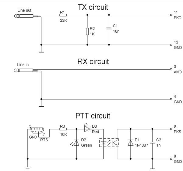
Image 1 Electrical wiring diagram with 9-pin D-Sub connector
Image 2 differs only in the PTT circuit. In the USB to FT232RL section, the FT232RL circuit with TLL logic levels allowing direct connection to the USB port was used. D2 is a classic semiconductor diode of practically any type. The circuit had the inverted RTS signal led out, so it is connected to the supply voltage.
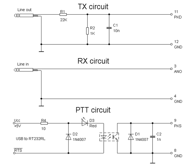
Image 2 Wiring diagram, PTT circuit has outputs to USB to UART converter of FT232RL type
Toľko k elektronickej časti. Istý čas mi zaberalo nastavenie a osvojenie si programu pre FT8, už spomínaného WSJT-X. The program comes with a complete and understandable manual, which is also translated into Czech. The setting itself consists in entering the call sign, selecting the PTT method (CAT, COM port or VOX) and selecting the input and output audio device. Those were the most necessary items, and those who are not afraid to experiment can try out the various functions the program is packed with. It was necessary to become familiar with the controls in order to know when to broadcast and when not to. It is known that many functions are automated, which does not prevent anyone from learning what is going on in the background. A detailed description of the controls is another chapter, there are plenty of available manuals. In addition to the mentioned manual, there is a summary of operating types from ZL2iFB in English.
Na záver môžem s istotou povedať, že zapojenie funguje, v súčasnosti používam zapojenie podľa obr. 2 . Už teraz mám za sebou pár pekných bežných, aj DX spojení. prevádzka z domácej stanice je takto obohatená o jeden nový mód.
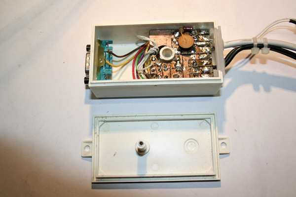
Open box (85 x 45 x 30). View from the side of the connections. The connections were made using the copper layer scraping technique. A half-sized box would be enough

CAT cable for controlling TCVR from applications. Since the notebook did not have a DE-9 serial connector, an RS232 to USB converter (black color) was used

Device for digimodes with cables. The white cable is used to connect the TCVR to the ACC2 connector. The connections of the audio signals from the TCVR and the laptop and the PTT circuit are located in a white box. An external sound card "3.5mm External USB to 3D Audio USB Sound Card Adapter 7.1 Channel Microphone" was used to connect the sound to the laptop. The PTT is connected to the laptop via a USB cable with the FT232RL circuit
Martin Jánoš, OM1MJ
References:
1 http://lea.hamradio.si/~s57nan/ham_radio/sb_intf/pcvk_sch.gif
2 http://ok1ufc.nagano.cz/EME_70_s/PTT_obvody/PTT.htm
3 https://www.QSL.net/zs1an/Soundcard.html
4 http://ok2pad.webz.cz/wsjtx.htm
5 https://www.g4ifb.com/FT8_Hinson_tips_for_HF_DXers.pdf