Verím, že mnohí návštevníci tohto portálu už čítali popis vysokoodolných predzosilňovačov od Robiho S53WW. Robi súhlasil s prekladom všetkých článkov, ktoré sa nachádzajú na jeho webe: http://lea.hamradio.si/~s53ww/. Ďakujeme!
V článku sa dočítate
Úvod
Javornik 144/14 MHz je vyskoodolný transvertor na 144 MHz optimalizovaný pre použitie s FT-1000MP ako stanicou na 14 MHz a stratou napájača 0,5 dB medzi anténou a vstupom transvertora (bez použitia prídavných predzosilňovačov!).
Má dva (synchrónne) RX konvertory s dostatočným ziskom aby prekonali aj šumové číslo FT-1000MP, ktoré je pri zapnutom IP0 18 dB. FT-1000MP bude vhodné málinko upraviť – vyviesť na zadný panel konektor so SUB RX tak, aby to nenarušilo výzor zariadenia.

TX konvertor si poradí so vstupnou úrovňou budiča na 14 MHz v rozsahu -20 dBm až +20 dBm. Budič s tranzistorom BFG196 pracuje v triede A a poskytuje veľmi čistý signál úrovne +15 dBm, ktorý stačí na vybudenie hybridu Mitsubishi M57727 (20W) alebo M57713 (10W).
RX konvertor

Schéma RX konvertora, prvá časť
Schéma RX konvertora, druhá časť
Celkové šumové číslo zostavy (0,5 dB straty v napájači + XVRT + IF RIG) je projektované na úroveň 2,0 dB (170K), čo je lepšie ako sa vyžaduje pre TROPO na 144 MHz. Straty 0,5 dB predstavuje napríklad 33m 7/8″ kábla, 18m 1/2″ kábla alebo 11m AircomPlus/H2000. Pamätajte, že investícia do dobrého (čítaj: hrubého) je oveľa lepšia ako investovať tú istú čiastku do predzosilňovača pod anténou! V prípadoch, kde nie je možnosť použiť krátky napájač obsahuje návrh spôsob pripojenia predzosilňovača 4xBF998 na anténny konektor (js napätie privádzané cez RX alebo RX/TX koaxiálny kábel).
Tabuľka 1: technické parametre RX časti Javornika 144/14 MHz:
|
JAVORNIK-144/14 |
JAVORNIK-144/14 + FT-1000MP (IPO ON, MAIN RX) |
|
|
NF |
0,9 dB |
1,5 dB |
|
G |
25,0 dB |
– |
|
input IP3 |
+ 4 dBm |
– 2 dBm (@15 kHz, calculated, based on my measurement of IP3 at 14 MHz) |
Zisk transvertoru sa nastavuje na vhodnejšiu úroveň pri použití iných typoch RIG-ov (tak, aby celkový dynamický rozsah bol čo najideálnejší) pomocou atenuátorov pred zmiešavačom. V nasledujúcej tabuľke nájdete hodnoty rezistorov pí-článku (R voči zemi/seriový R) pre rôzne šumové čísla RIG-ov tak, aby celkové šumové číslo bolo 1,5 dB.
Tabuľka 2: hodnoty rezistorov pí-článku pred zmiešavačom na dosiahnutie celkového šumového čísla 1,5 dB:
| G [dB] |
NF [dB] |
T [K] |
IP3out [dBm] |
ATT [dB] |
PI ATT R values |
IF RIG NF [dB] |
|
26,5 |
0,75 |
55 |
30 |
2,5 |
330/15 |
20 |
|
26,0 |
0,8 |
58 |
30 |
3,0 |
300/18 |
19 |
|
25,5 |
0,85 |
63 |
30 |
3,5 |
270/22 |
18 |
|
25,0 |
0,9 |
67 |
29 |
4,0 |
240/27 |
18 |
|
24,5 |
0,95 |
71 |
29 |
4,5 |
220/30 |
17 |
|
24,0 |
1,0 |
75 |
29 |
5,0 |
200/33 |
16 |
|
23,5 |
1,05 |
79 |
29 |
5,5 |
180/36 |
15 |
|
23,0 |
1,1 |
84 |
28 |
6,0 |
150/39 |
14 |
|
22,5 |
1,2 |
92 |
28 |
6,5 |
150/43 |
13 |
|
22,0 |
1,3 |
101 |
28 |
7,0 |
135/47 |
11 |
|
21,5 |
1,35 |
106 |
28 |
7,5 |
130/51 |
9 |
|
21,0 |
1,45 |
115 |
27 |
8,0 |
120/56 |
5 |
Ak bude útlm koaxiálneho kábla väčší ako 0,5 dB, na prepočítanie potrebného zisku XVRT pri požadovanom NF okolo 2,0 dB (T=170K) použite nasledujúci vzorec:
TIF/G + TRX = T
T = 170 – 290*(10L/10 – 1)
Kde TIF = 290*(10NF/10 – 1) a TRX je funkciou zisku (G) podľa Tabuľky č.2.
Napríklad: TIF = 11200 K (16 dB) and L = 0,8 dB ==> T = (170 – 58) = 111 ==> Najprv vyskúšame s G = 446 (26,5 dB) and T RX = 55 K dá T = 80 čo je primálo a tak vyskúšame ďalšiu hodnotu z Tabuľky 2 a počítame dovtedy, kým sa nedopracujeme ku G = 281 (24,5 dB) and T RX = 71 K, čo vyhovuje obidvom podmienkam.
Zistenie hodnoty šumového čísla HF RIG-u je zložitejšie ako sa môže zdať. Údaje z recenzií od G3SJX a ARRL vychádzajú z citlivosti, G3SJX pri 10 dB (S+N)/N na SSB (BW = 2,4 kHz) a ARRL pri 0 dB S/N na CW (BW=500 Hz). Za predpokladu, že šumová šírka je rovnaká ako je šírka filtrov (2400 alebo 500 Hz) si každý môže ľahko spočítať šumové číslo (napríklad pre údaje ARRL platí NF = MDS – (-174 + 10LOG(BW))). Ale šírka prenášaného pásma šumu nie je rovnaká, tento fakt je viditeľný aj pri porovnávaní vypočítaných šumových čísel podľa údajov ARRL a G3SJX. V Tabuľke 3 je pre porovnanie niekoľko vypočítaných hodnôt HF RIG-ov. BW šumu je jasne ovplyvňované medzifrekvenčnými obvodmi. Ešte chcem povedať, že NF vypočítané z údfajov od G3SJX sú príliš optimistické, pretože AF obvody zužujú BW a tak niektoré čísla nie sú odhaliteľné (IC-775, TS-870).
Tabuľka 3: hodnoty NF rôznych HF RIG-ov na 14 MHz pri zapnutom AIP (predzosilňovač OFF) vypočítané z údajov G3SJX a meraní ARRL pri predpoklade, že BW šumu a IF filtrov je zhodné:
|
HF RIG |
NF [dB] podľa dát G3SJX (BW = 2,4 kHz) |
NF [dB] podľa dát ARRL BW = 500 Hz) |
|
FT-1000MP |
16 |
19 |
|
FT-1000MP MARK-V |
17 |
20 |
|
TS-870 |
18 |
18 |
|
IC-775DSP |
12 |
9 |
|
IC-756PRO |
12 |
13 |
|
IC-738/736 |
12 |
14 |
Prečo 14 MHz medzifrekvencia a nie štandardná 28 MHz? Pretože linearita prijímačov HF RIG-ov je optimalizovaná pre 7 a 14 MHz. Na nižších pásmach je ju možné zlepšiť zaradením atenuátorov pri znížení citlivosti. Linearita na vyšších pásmach niektorých zariadení je zlá (bez akéhokoľvek dobrého technického vysvetlenia). Konkrétne linearita novších zariadení na 28 MHz je veľmi zlá (s výnimkou TS-870). Tabuľka 4 dáva odpoveď, ako je to IP3 rozličných HF zariadení.
Tabuľka 4: hodnoty IP3 rôznych HF RIG-ov na 14 a 28 MHz pri AIP ON (predzosilňovač OFF) ako ich udáva G3SJX (vzdialenosť signálov 50 kHz):
|
HF RIG |
IP3 [dBm] @ 14 MHz |
IP3 [dBm] @ 28 MHz |
|
FT-1000MP |
24 |
6 |
|
FT-1000MP MARK-V |
24 |
2 |
|
TS-870 |
17 |
20 |
|
TS-850 |
25 |
16 |
|
IC-775DSP |
12 |
1 |
|
IC-756PRO |
13 |
14 |
|
IC-738/736 |
21 |
22 |
Teraz si poďme porovnať zostavy VHF pracoviska s 0,5 decibelovou stratou koaxiálneho kábla, XVRT a HF RIG-om pri použití Javornik-u 144/14 a LT2S. LT2S je uznávaný ako dobrý „štandardný“ transvertor so zsikom 20 dB, šumovým číslom 1,0 dB a IP3out +27 dBm. V tabuľke 5 sú údaje o NF a IP3in pri použití Javornik-a 144/14 a LT2S s rôznymi KV zariadeniami (údaje o NF a IP3 sú z tabuľky číslo 3 a 4). Pretože LT2S má príliš veľký zisk pre niektoré KV zariadenia bude celková citlivosť prinízka (záleží na šume antény, čo sa geograficky rôzni). Údaje v zátvorkách platia pre Javornik 144/14 so ziskom nastaveným na takú hodnotu, aby NF bolo zhodné s LT2S. Údaje pre Javornik 144/14 sú v samostatnom stĺpci. Pozorným porovnaním je možné vidieť, že zisk a NF XVRT má vplyv na celkovú hodnotu RX systému.
Napríklad vezmime si FT-1000MP s LT2S: môže sa zdať, že citlivosť bude slabá a tak by sme okamžite pridali predzosilňovač so ziskom 10 dB ku anténe. Linearita sa v tom prípade zhorší o 10 dB (IP3in = -23 dBm) aj keď je predzosilňovač perfektne lineárny. Prípadne zapne na FT-1000MP predzosilňovač (IP0 je OFF) – v tom prípade IF NF klesne z 18 dB na 8 dB a celkové NF z 3,2 dB na 1,7 dB. Ale! IP3 tiež klesne z +6 dBm na -1 dBm a celková linearita klesne zhruba na úroveň -20 dBm! Nakoniec je možné uzavrieť, že LT2S je možné použiť iba s KV zariadeniami, ktorých NF je 10-14 dB a IP3 hodnoty sú nejakých +20 dBm (na 28 MHz!!!).
Tabuľka 5: hodnoty NF a IP3 pri použití Javornik-a 144/14 na 14 MHz a LT2S na 28 MHz:
|
HF RIG
|
JAVORNIK-144/14 |
LT2S |
|||
|
NF [dB] |
IP3 [dBm] |
G [dB] |
NF [dB] |
IP3 [dBm] |
|
|
FT-1000MP |
2,0 (3,2) |
-2 (+2) |
25 (21) |
3,2 |
-13 |
|
TS-870 |
2,0 (3,2) |
-8 (-4) |
25 (21) |
3,2 |
+0 |
|
TS-850 |
2,0 (2,7) |
+0 (+2) |
24 (21) |
2,7 |
-4 |
|
IC-775DSP |
2,0 (1,8) |
-9 (-10) |
22 (23) |
1,8 |
-18 |
|
IC-756PRO |
2,0 (2,1) |
-9 (-9) |
22,5 (22) |
2,1 |
-6 |
|
IC-738/736 |
2,0 (2,2) |
-2 (-1) |
22,5 (21,5) |
2,2 |
+1 |
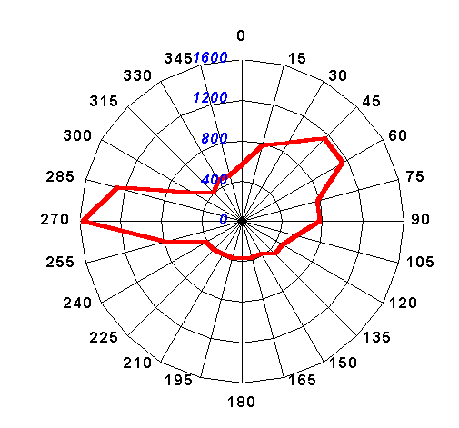
 Pri úvahách o požadovanej citlivosti na 144 MHz v contestoch musíme vziať v úvahu aj tepelný šum antény (TA). V niektorých prameňoch sa udáva minimálne TA na 144 MHz 200K, ak je anténa nasmerovaná na chladnú oblasť oblohy. Skutočnosť je vždy ale o niečo horšia. Na obrázku môžete vidieť TA na našom contestovom pracovisku JN75DS, 1269 m asl pri meraní 2.7.1999 o 19.00 LT. Najnižšia nameraná hodnota bola 370K, čo je ekvivalentné 3,5 dB NF. Maximálne hodnoty sú v smere mesta Postojna (zhruba 10 km, 500m asl) 1600K = 8,1 dB a miest Cerknica/Ljubjana.
Je známe, že ak šum RX sytému je zhodný so šumom antény, potom zhoršenie S/N je 3 dB. Je diskutabilné, aké zhoršenie S/N je prijateľné pre VHF contesting. Ja si myslím, že TRX by malo byť 0,6-krát z hodnoty TAmin – dáva zhoršenie S/N o 2 dB. A TAmin je brané ako 300/2 + 200/2 = 250K (polovica šumu zeme a polovica šumu oblohy). V prípade NF systému 2,0 dB (170K) tak máme dostatočnú rezervu na nepredvídateľné straty v relé, prepojkách a podobne.
Lokálne oscilátory

Schéma oscilátora, prvá časť
Schéma oscilátora, druhá časť
Schéma T/R prepínania
Schéma prepojenia XVRT
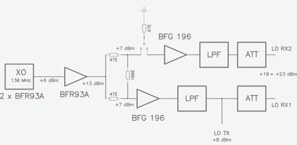
Lokálne oscilátory (130 MHz) sú v zapojení podľa Buttlera s nízkošumovými tranzistormi BFR93a. Zapojenie má dva separátne oscilátory pre dva RX zmiešavače. Maximálna úroveň budenia z LO má byť 23 dBm, ktorú nastavíme atenuátormi pred zmiešavačmi. Je možné použiť rôzne zmiešavače (odporúčam TUF-1H). Pri použití 23 dBm zmiešavača (napr.RAY-1 alebo SAY-1) je možné dosiahnuť zvýšenie hodnoty IP3 o 1 alebo 2 dB (vlastného RX konvertora, pretože IP3 je určené IF RIG-om tak, že je nižšia ako +25 dBm). Nie je však na škodu použiť RAY-1 pri rovnakom budení ako TUF-1H (+14 dBm) – je lepšie použiť SAY-1 ako pre +20 dBm P1dB. Akokoľvek, cena +23 dBm LO zmiešavača nestojí za zlepšenie o 1-2 dB IP3.
Ak nemáte záujem o obidva RX konvertory, potom stačí skonštruovať iba jednu časť.
TX konvertor

Schéma TX konvertora, prvá časť
Schéma TX konvertora, druhá časť
Schéma PA TX konverora
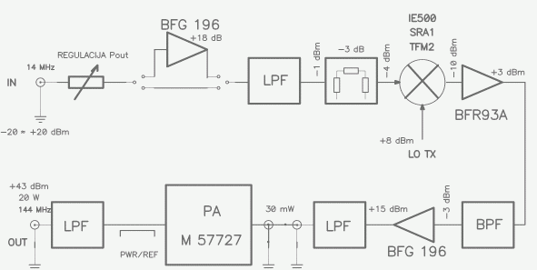
TX konvertor dokáže spracovať budiaci signál 14 MHz v úrovniach od -20 dBm po +20 dBm. Pre TRX, ktorý má veľmi nízku úroveň signálu (-10 až -20 dBm) je možné zaradiť zosilňovací stupeň. Za nízkoúrovňovým zmiešavačom je zaradený nízkošumový širokopásmový zosilňovač. Budič pracuje v triede A s BFG196 a poskytuje veľmi čistý signál úrovne +15 dBm (IMD5 je okolo -60 dBc). Na koncový stupeň je najefektívnejšie použiť bezproblémový hybridný PA od Mitsubishi M57727 (20W) alebo M57713 (10W). Nie je to najlepšie technické riešenie, pretože moduly nie sú najlineárnejšie, ale pri výkone 20/10W či menej je ľahké dosiahnuť potlačenie vyšších IMD produktov o viac ako 120 dB pod úrovňou nosnej (čo stačí na to, aby sme blízkym staniciam nespletrovali).
Najväčším problémom celej TX časti je širokopásmový šum. Sú dva zdroje, ktoré sa podieľajú na jeho produkcii: XVRT a HF RIG. Meraním Javornika 144/14 MHz pri výstupnom výkone 20W bola dosiahnutá hodnota -118 dBc/2,4 kHz a môže byť ešte zlepšená o 10-15 dB použitím TX zmiešavača s vyššou oscilátorovou úrovňou (pozor – šum TX bude len -108 dBc/2,4 kHz pri výstupnom výkone 2W!). Šumové spektrum HF RIG-u je ale oveľa horšie! Pohľadom do údajov od G3SJX (ARRL meria TX šum iba vo vzdialenosti do 20 kHz, čo je možné považovať iba za fázový šum, nie širokopásmový TX šum) je možné vidieť, že žiadny z moderných RIG-ov nemá širokopásmový TX šum lepší ako -110 dBc/2,4 kHz vo vzdialenosti 200 kHz od nosnej frekvencie. V užšom rozsahu je okolo 100 dBc/2,4 kHz, čo stále nie je hodnota prevládajúceho fázového šumu. Znamená to, že pomer S/N vysielaného signálu je iba 100 -110 dB!!! Dve 500W VHF stanice so 16 dBi anténami vo vzdialenosti 100 km (!) s rádiovou viditeľnosťou vyprodukujú signál o sile -27 dBm – čo je 111 dB nad úrovňou SSB šumu (beriem citlivosť -138 dBm). Iba stlačením PTT na zariadení s úrovňou vysielaného šumu -111 dBc/2,4 kHz bude znamenať u protistanice zvýšenie šumu o 3 dB!
Niekto by mohol usudzovať, že širokopásmový TX šum je najmä problém počas VHF contestov v obsadenejších oblastiach. Napríklad, v S5 je priemerne vzdialenosť medzi dobre vybavenými stanicami 50 km a vzdialenosti 10-20km nie sú žiadnou zvláštnosťou!
Prepojenie JAVORNIK-a 144/14 a FT-1000MP
Na to, aby sme plne využili možnosti FT-1000MP so dvoma separátnymi RX vstupmi budeme potrebovať jednoduchý obvod, ktorým spojíme XVRT a IF RIG. Za minimum je možné považovať krížový prepínač na 14 MHz, ktorý v jednej polohe spojí oba RX konvertory na vstup MAIN RX. To z dôvodu, že SUB RX nemá rovnakú kvalitu ako MAIN RX a neposkytuje DSP. Odhadujem ale, že iba pri 20% spojení prepnem zo SUB na MAIN RX.
Interface môže tiež obsahovať obvod, ktorý umožní pracovať systémom S&P na SUB RX s oboma RX konvertormi nezávisle na prepínači s kvalitným NB, kryštálovými filtrami a pod.
Ďalší vývoj
Týka sa problémov s vysielaným širokopásmovým šumom. V úvahu prichádza skonštruovať vysokokvalitné VFO na 130 MHz (radšej VXO alebo DDS/PLL) a použiť HF RIG na jedinej frekvencii. V tom prípade by bolo možné zaradiť na 14 MHz kryštálový filter medzi RIG a XVRT. Výsledkom by bol lepší pomer S/N vysielaného signálu a nižšia úroveň IMD produktov pri príjme.
Robi, S53WW
Slovenský preklad Viliam, OM3-0122
