Používam PSK31 odkedy som ho pred pár rokmi vyskúšal. Je to jeden úžasný mód ak robíte radi veci digitálnym spôsobom, páči sa vám klávesnicové QSO a viete že päť wattov vás môže preniesť kdekoľvek na svete.
Mám rád súťaže aj dlhé večery s QSO aby som sa dozvedel ako sa žije inde na svete. Môj problém spočíval v tom, že som bol brzdený opätovným vylaďovaním signálu. Nie vysielačkou, ale úrovňou audio nastavenia zvukovej karty. Zo začiatku som nastavoval vo Windows audio výstup na maximum, aby som získal z vysielačky čo najvyšší výkon. No dozvedel som sa že to nie je až taký dobrý nápad- ak takto premáhate zariadenie, môže to spôsobiť vytvorenie veľkého množstva splateru a 31 Hz signál môže byť široký až niekoľko stoviek Hz, čo znemožní vykonávať ďalšie spojenia. Priniesol som si z práce osciloskop a pozrel som sa na RF výstup pri maximálnom vyťažení. Bol to klasický prípad prerušovanej sínusoidy. Riešením tejto situácie je udržať tie nastavenia zvukovej karty dole, nie na maxime. Na mieste je však otázka – nakoľko dole? Pri malom audio výstupe nevychádza zo zariadenia nič alebo skoro nič. Takže môj drahý osciloskop sedel dobre s mojím zariadením a mohol som sledovať RF výstup a upraviť tak nastavenie zvukového výstupu až kým som nedostal krásnu sínusoidu bez prerušovania.
Takto som mohol vyrátať môj priemerný výstup (P=E**/2R) a samozrejme že som dosiahol dobrý signál. Jedinou slabinou bolo, že môj osciloskop plnil len jeden účel. Tak som dostal nápad nahradiť indikátor PIC mikroprocesorom. Veľa PIC má zabudovaných ADC, no aj tak nie sú dosť výkonné na samplovanie 14 Mhz signálu. Mňa zaujímal predovšetkým obal krivky, čo znamená že musím usmerňovať signál a ísť cez RC filter na ADC. Potom som naprogramoval firmware mikroprocesora presne tak, aby umožňoval 64 vzoriek RF na 1 milisekundové intervaly- presne dva PSK31 bity. Tento buffer bol potom nahraný do PC prostredníctvom sériového portu. Potom som napísal software založený na Fourierovej transformácii, ktorý analyzuje harmonické frekvencie a vypočítava IMD (intermodulačné skreslenie). Na začiatku aplikácia ukázala len vlnovku a odporúčala znížiť alebo zvýšiť hlasitosť zvukovej karty aby sa dosiahla perfektná modulácia. Neskôr som zistil, že môj program má zabezpečený prístup k zvukovej karte cez Windows API a táto aplikácia mi umožňuje sama upraviť nastavenia výstupu zvukovej karty. Keď som sa spätne pozrel na program, fungovalo to. Môj PSK31 signál bol permanentne perfektný bez toho aby som sa zase nad niečím rozčuľoval.
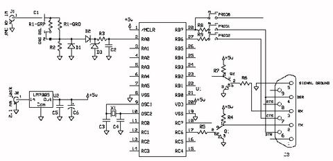
Obvod pre malý PSKmeter vyzerá asi takto:

Ja to cechom jednoduché: D1 a D2 zabezpečujú usmerňovanie a R3 + C2 zase filtráciu. PIC využíva 2n2202 NPN tranzistor na chod RS-232 spojenia s počítačom. Aj keď použitie tranzistorov na prepínanie medzi +5V a zemou technicky nie je správne pre RS-232 (kde je lepšie prepínanie medzi +12 a –12), pracuje to dobre a je to lacnejšie ako použitie MAXIM interface chip.
Súbor s mikroprogramovým vybavením môžete nájsť na: https://www.agurk.dk/bjarke/Projects/PSK-meter/PSKMeter.hex, takže si môžete postaviť obvod a naprogramovať chip, čo je vlastne hardware.
Aplikácia vo Windowse vyzerá asi takto:

Kontaktoval som niekoľko miestnych rádio klubov a potom Pacificon 2002 a rádioamatéri sa ma stále pýtajú, či by som mohol urobiť stavebnicu. Trochu som sa zdráhal, pretože si to vyžadovalo oveľa viac práce: dizajn a vymyslieť výrobu plošného spoja, kontrolu kvality, kompletný manuál atď. Čo ma presvedčilo vyskúšať to, bol úžasný software na https://www.expresspcb.com. Tento bezplatný software mi umožnil navrhnúť obvod a zvýrazniť plošný spoj. O dva dni mi prišli spoje mailom. Je to veľmi podobné ako posielať súbor do tlačiarne s tým rozdielom, že tlačiareň je v inom meste. Dobré, nie?
Po niekoľkých interakciách a revíziách som dostal takúto počítačovú dosku:

George Rothbart (KF6VSG)
Translated by XY of MW3SDO, revised by MW3SDO