This article is by Robi, S53WWThe original in English can be found on his website: https://lea.hamradio.si/~S53WW/. You could have already read two great articles from Robi on this portal (preamps S53WW and XVRT Javornik) - and the third one is also excellent. Thank you Robi!
1. A few words about 2m contesting in EU
Every serious 2m Contestman must come before this question - what type of antenna is best for my contest QTH? The quick answer is pressing - with the highest gain possible! The answer is correct only for stations that are 800km and more away from the locations with the highest activity. These are mainly DL and OK, then locations outside Central Europe. However, if several directions come from your contest QTH, which bring a significant amount of points (large number QSO*QRB), then the most important feature of the antenna used is the width of the main radiation lobe for -3 dB.
The picture shows more or less a common directional diagram of connections for a typical contest QTH in S5 (Alps at azimuth 300°, Balkan mountains and Adriatic Sea at azimuth 120 - 180°). From the statistics on the left side of the picture, it can be seen that about 60% of points are obtained from three directions, which have a width of about 30° (this statistic is calculated by the program VHFSTAT.EXE from data in EDI format, conversion from EDI to QSO/TST format is possible with VHFLIB.EXE. According to this diagram, it can be definitively determined that it is necessary to have two antenna systems - one with a 30° lobe width and the other with a 75° lobe width. At this point, the question of interference from nearby stations arises when using a 75° lobe antenna. It is important to use an RX with excellent dynamic range (which of course excludes preamplifiers). The deployment of home made RX seems to be the best, but the composition of XVRT+HF RIG with a noise figure of around 2.0 dB is also OK. Total setup noise (coax attenuation plus RX noise) may not be below 2.0dB if the transverter gain exceeds the dynamic range of the receiver (turbo deluxe XVRT and super HF RIG are degraded to mid-range - otherwise completely linear preamplifier - is included for them!)
At least twoIndependent receivers are required for efficient use of three or four antenna systems (of course, with a second operator). If all RX operators can also transmit, it is the most optimal solution, although not necessary.
Minimum gain of the antenna for tropo contest is about 16 dBi. This gain is achievable with a long Yagi (4 lambda), but its beamwidth for -3 dB (in the E plane) is less than 30°. How to achieve azimuth coverage in the range of 50 - 70° and gain higher than 16 dBi? The answer is I-stack (vertical system) of short yagi antennas.
2. I-stack of four 4 el. yagi antennas with maximum gain
After a thorough review of our contest QTH (S59DEM/JN75DS) according to the directional connection diagram, I decided to build a vertical system of a quad of short yagis, which have a main lobe width for -3 dB of about 50°. To achieve the desired gain, I chose the yagi version with maximum gain. The maximum gain is when the antenna impedance is below 50 ohms. With a considered fixed antenna impedance of 12.5 ohms, it is possible to obtain 50 ohms by using a folded dipole and a simple coil balun. In that case, it is possible to build an antenna that has an impedance of 50 ohms, a gain of 11.3 dBi, a lobe width of 50° in the E plane and a length of 1600 mm (0.8 lambda). Simulated And in the H plane you can see the directional characteristics in the attached images.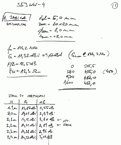
Fig.2 - stacking characteristics of two 4 el. yagis with maximum gain versus vertical distance. The boom is made of Al profile 20x20 mm, elements made of Al rod with a diameter of 5.0 mm are isolated from the boom (boom correction is 2.0 mm). Plastic brackets (home-made) were used as element insulators. This technology proved to be mechanically unstable, so the elements and insulators were later glued to the boom with a two-component adhesive.
The shadow side of short yagis with maximum gain is narrow bandwidth (144 - 145 for PSV 1:1.5) and poor front-to-back ratio (for example, 12.5 dB for this design). However, since the use of a single antenna is not intended, but an antenna system, the problem with the F/B ratio can be effectively solved by suitable stacking. The proposed system also improves PSV (due to reactive component compensation) - PSV 1:1 across the entire range of 143 - 146 MHz. Individual antennas can be horizontally spaced lambda/quarter and powered in the correct phase. In that case, the F/B ratio is 25 to 30 dB. Vertical stacking is shown in figure 3.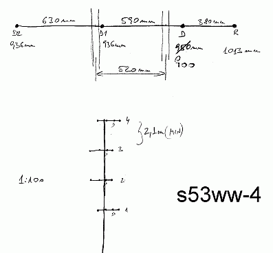
dimensions of I-stack of four 4 el. Yagis. Note that the vertical separation of antennas is at least 2.1m and can be increased to 2.4m with a gain increment of 0.1dB/0.1m. In the top part of the diagram, positions where the tower intersects with the boom can be seen. The top and bottom antennas are attached to the tower between D1 and D2, the middle antennas are shifted forward by 520 mm. For this reason, cables feeding the middle antennas should be electrically length lambda/4 shorter (meaning that the cables should be 520mm*velocity_factor (340 mm for cables with solid PE, dielectric and 360 mm solid PTFE). dielektrikom a 360 mm pevné PTFE).
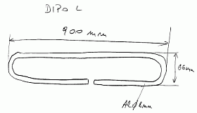 The dipole (in Fig. 4) is a classic folded dipole with the same dimensions as DJ9BV antennas, but with a length of 900 mmabalun it is made up of a coil from RG-188/RG-316 cable (Fig. 5). The dipole is connected to the boom directly (the dipole tube is crimped and drilled in the middle at a length of 25 mm. It is fixed to the boom with a suitable screw.). The same technique is also used for connecting the balun to the dipole.
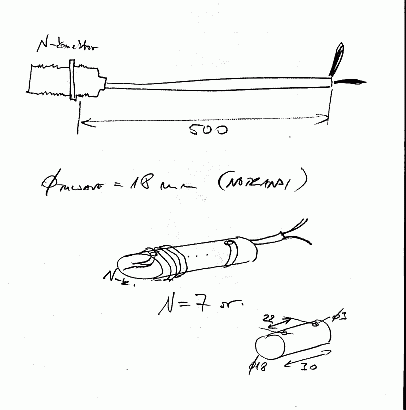
Fig. 5 - detail of the coil balun: a seven-turn coil is wound from a 500 mm long thin Teflon cable (e.g. RG-188) on a plastic body with a diameter of 18 mm (plastic pipe for home installations) with pre-drilled holes at a distance of 22 mm, which serve to fix the cable. The N-connector is directly connected to the RG-188.
Finished balun it is covered with an electrical installation plastic box. The detail of the dipole with the balun is shown HERE. The author with an antenna at the Ljubljana Faculty of Electrical Engineering is HERE.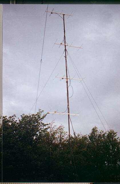
This antenna system has proven itself in contests (S59DEM/S55A/S53WW) over the last two years compared to a single 15 el. DL6WU. Our main antenna system consists of two 15 el. DL6WU stacked vertically. It has about 3 dB higher gain (4x4 has a longer feeder, approx. 0.5 dB and only RG-213 as stacking cables (from the old 4x6 el. system)).
Robi, S53WW
https://lea.hamradio.si/~S53WW/
Slovak translation by Viliam, OM0AAO
