WIFI, wi-fi, mikrovlnka, bezdrôtový internet sú synonymá pre prenos dát (internetu) éterom na pomerne vysokých frekvenciách. Výhodou je najmä mobilita v kombinácii s vysokou prenosovou rýchlosťou (rýchlosť prístupu na internet býva limitovaná providerom).
Siete najpoužívanejších štandarov 802.11b a 802.11g pracujú na frekvencii 2,45 GHz. To nie je veľmi vzdialené rádioamatérskemu pásmu 13 cm a tak platia všetky zákonitosti ako pre toto mikrovlnné pásmo.
Najväčším problémom WIFI je šírenie signálu v priestore. Pokiaľ sa neuspokojíme s dosahom do niekoľko metrov (desiatok metrov), je potrebné uvažovať o výkonnejšej anténe. Komerčne sa na strane klienta používajú najmä smerové antény yagi a paraboly. Ich cena je však pomerne vysoká.

Porovnával som tri antény – originálnu dodávanú s AP, homemade DL7KM (osmička) a 10-elementového loop quada, ktorý sa vynikajúco osvedčil. Najlepší DX, ktorý som na túto anténu robil je AP vo vzdialenosti 4,5 km.
Konštrukčne je anténa jednoduchá (jednoduchšia ako vyzerá), vyžaduje bežné mechanické náradie a väčšiu pájku (viac ako 100W).
V článku sa dočítate
WIFI anténa podľa G6KSN
Inšpiráciou k danej anténe je materiál na http://www.paramowifix.net/antenas/loop_uda_yagi/. Je to design G6KSN prepočítaný na frekvenciu podľa potreby. Tu popisovaná verzia je dosť dlhá.
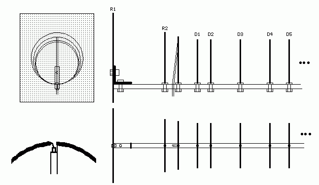
Vďaka programu LoopYagi Design od G6KSN si môžeme anténu spočítať na ľubovoľnú frekvenciu s ľubovoľnou dĺžkou boom-u. V mojom prípade je to 10-elementová verzia. Počet prvkov určila dĺžka medenej nosnej rúrky – boom-u. Celá anténa nie je dlhšia ako tridsať centimetrov.

Rozmery vypočítané programom


Na boom-e si naznačíme pilníkom pozície jednotlivých prvkov. Ryhy urobíme radšej dlhšie, aby ich bolo pri letovaní dobre vidieť.
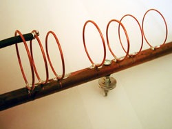
Na prvky použijeme Cu vodič s priemerom 1,5 mm. Krúžok vyrobíme takto: z drôtu odstrihneme presnú dĺžku vodiča na prvok (napr. 135 mm) a ten zohneme na rúrke vhodného priemeru. Po uvoľnení z kliešťov drôt odpruží, preto je vhodnejšie použiť rúrku menšieho priemeru ako je prvok. Takto si nachystáme všetky prvky, aj žiarič.

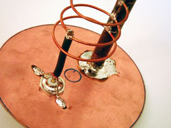
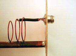
Veľkou pájkou potom stačí už len prvky naletovať na boom. Po zaletovaní všetkých prvkov rozstrihneme presne oproti boomu žiarič (môžeme aj 1 mm vyštiknúť). Namontujeme N-konektor. Z tenkého koaxiálneho káblika (dá sa použiť aj RG-58 ak nie je lepší) vyrobíme prepojku. Všetky vývody skracujeme na minimum. Káblik zaletujeme.
Mechanická konštrukcia je zrejmá z fotografií
|
|
|
|
|
|
Program Loop Yagi CALC si môžete stiahnuť .: TU :.. Anténa bola vyskúšaná s výbornými výsledkami len na WIFI, na AMA zatiaľ nie. Pri WIFI je badateľný vplyv polarizácie (vertikálne, horizontálne, „a niečo medzi tým“) a smerovosť. Nastavenie na najlepší signál si vyžaduje trocha trpezlivosti.
Pre vonkajšie použitie ju nezabudnite dobre zafixovať proti vlhkosti.


