
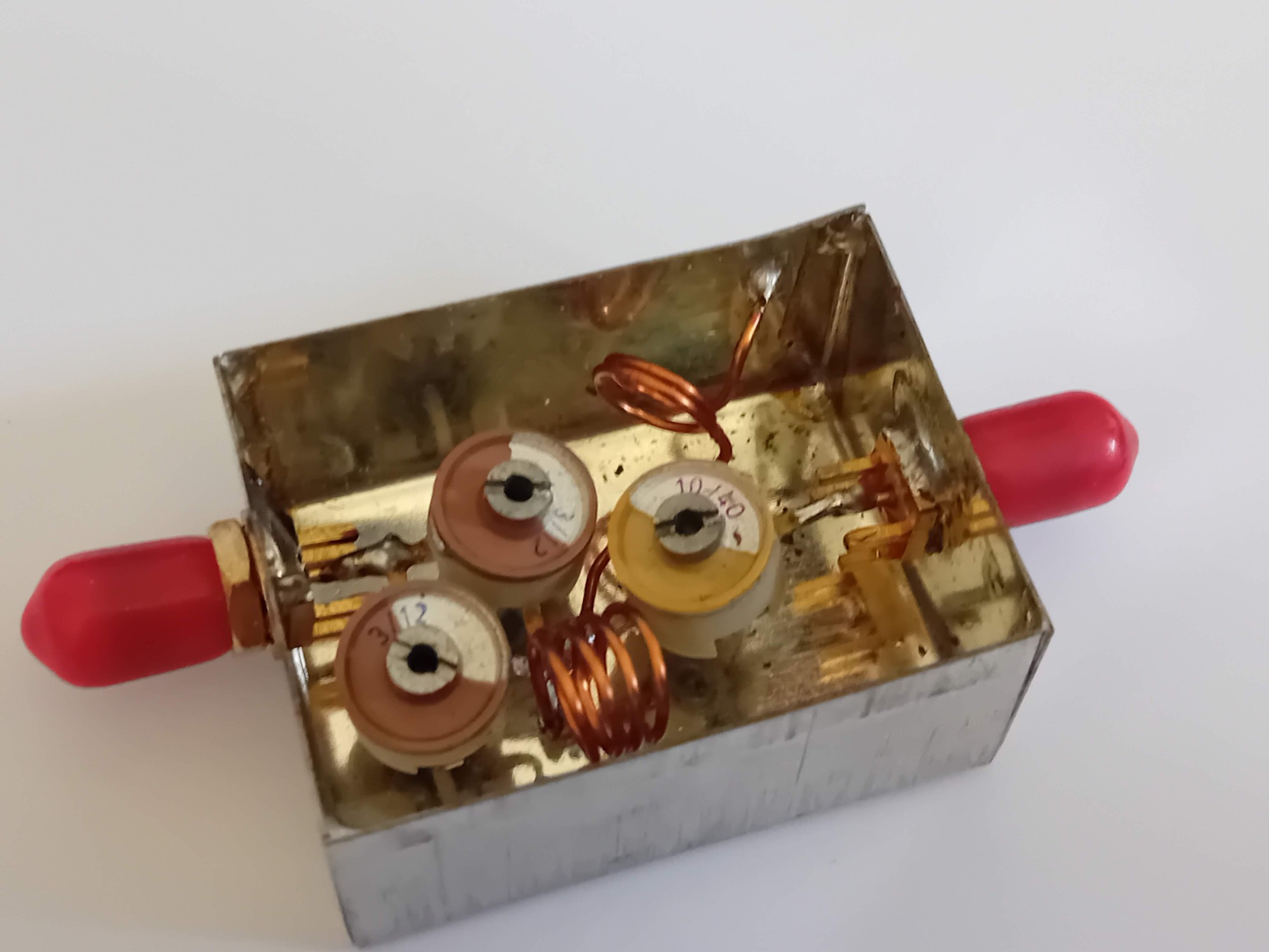
During simultaneous operation on 144 and 432 MHz, a signal outside the receiver's operating band can also be a problem. A typical example is a satellite or VHF station where operations are conducted on both bands simultaneously and antennas are placed relatively close together. A strong signal from a 2 m transmitter can enter the 70 cm receiver input and cause it to wake up or behave non-linearly.
This problem is addressed by combined filter according to the design VE2ZAZ. In the path for 432 MHz, it creates a high-pass characteristic while simultaneously providing a very narrow notch in the 144 MHz area. The result is a very low insertion loss in the 70 cm operating band while significantly suppressing a strong 2 m signal. The design arose from a practical need for operation on both bands and was subsequently used by other radio amateurs.
In the article you will read
Why a filter for satellite and multi-band operation?

During satellite operation it is common for one system to operate simultaneously on 2 m and 70 cm. When using separate antennas, the distance between them can be small, and with directional antennas, one antenna can directly 'see' the other. The resulting coupling may not be a problem only at the fundamental frequency itself. A strong 144 MHz signal can directly enter the 432 MHz receiver input, where it is no longer a classic problem of insufficient harmonic filtering.
This phenomenon describes OK2VMC from experiences of VHF contests. At its location, the antennas were close together and approximately 300 W was used at 2 m. Measurements showed that the suppression of the third harmonic of the 2 m transmitters was 72 to 77 dB, so the source of broadband interference was not the third harmonic. The problem was the strong 144 MHz signal penetrating through the insufficient selectivity of the 70 cm receiver input.
This is also important for understanding the concept of the filter. It is not primarily a filter against the third harmonic of 144 MHz. Its task is to prevent the fundamental 144 MHz signal from penetrating into the 432 MHz receiving path and awakening its input circuits or LNA.
The advantage of combining a high-pass filter and a notch
The high-pass filter itself would suppress lower frequencies, but with the requirement for significant suppression of 144 MHz, a compromise may be needed between the steepness of the characteristic, insertion loss, and bandwidth. VE2ZAZ addresses the problem by combining the high-pass effect and the resonant notch exactly in the 2 m range.
The result is a filter that can have very low insertion loss at 432 MHz while providing tens of decibels of suppression at 144 MHz. The reference design description states approximately 0.1 dB insertion loss at 432 MHz and approximately 60 dB suppression at 144 MHz. These values should be understood as the result of a specific tuned specimen, not as automatically guaranteed parameters of every manufactured filter.
Principle of connection
The VE2ZAZ filter is simple. The entire circuit is passive and does not require any power supply.

For 432 MHz, the resulting network represents a through path with low insertion loss. At 144 MHz, the individual reactances enter into a resonant relationship, which creates a deep attenuation notch. The exact position of the minimum is very sensitive to the actual values of the components, parasitic capacitances, inductances and mechanical design.
That is why such a filter cannot be built solely based on the nominal values of components and expect an identical result. In VHF and UHF, mechanical dimensions, lead lengths, type of trimmer, placement of the coil, and mutual positioning of components are part of the RF circuit.
Construction of filter VE2ZAZ
The original design VE2ZAZ uses two wound parallel coils and three adjustable capacitors. These components allow the filter to be tuned to a specific operating band.
Construction details
For L1 and L2
- Use AWG18 wire (0.042″ / approximately 1 mm diameter).
- Wind the coils to a diameter of 0.25″ (6 mm).
- Set the spacing of the turns to approximately the diameter of the wire used.
- Choose the number of turns according to the data provided in the diagram.
For C1, C2, and C3
- Choose a variable capacitor with a range that includes the specified value.
- Recommended values for variable capacitors are provided in parentheses.
Note: The schematic lists values for the coils as L1 = 18 nH / 2 turns and L2 = 44 nH / 3 turns. For the capacitors, the recommended ranges are C1: 9–35 pF, C2: 2–8 pF, and C3: 9–35 pF.
In construction, not only the electrical schematic is essential, but also the mechanical realization. The filter must be housed in a metal enclosure with good grounding and short connections. The metal casing itself is not electrically neutral. In similar UHF filters, it can change parasitic capacitances and return currents, thus shifting the resonant frequency. For example, in a later PCB version derived from VE2ZAZ, a shift of the notch by approximately 5 MHz was observed after placing it in a metal enclosure.
This property explains why it is advisable to tune the filter only in the final mechanical configuration. If a change is made after closing the enclosure, the resulting characteristic may differ from what could be measured on an open test fixture.
Tuning and results
The most practical tool for tuning is a VNA. OK2VMC statesHe noted that he tuned the filter using a cheap Chinese VNA and that without the VNA, tuning would essentially be a blind operation. In his implementation, he used ceramic capacitive trimmers and coils made of enameled wire with a diameter of 1 mm. The result was a suppression of 144 MHz greater than 48 dB, insertion loss at 70 cm of approximately 0.17 dB, and return loss of approximately 37 dB.
When tuning, it is tempting to set the filter for the deepest notch possible. However, this may not be the best solution for real operation. OK2VMC reports that after deploying the filter, interference disappeared when the 2 m antenna was pointed towards the 70 cm antenna. The filter also handled approximately 75 W in this configuration over the long term.
In proposals of this type, it is therefore more reasonable to monitor not only the absolute minimum S21 at 144 MHz but also the width and stability of the notch and simultaneously the minimum insertion loss across the entire desired range of 432 MHz.
Practical experiences OK2VMC
OK2VMC originally dealt with interference of the 70 cm station during the operation of the 2 m transmitter. After verifying that the 2 m transmitters themselves do not create a problematic third harmonic, he focused on the resilience of the 70 cm receiving path. The filter according to VE2ZAZ was then directly incorporated into the antenna coaxial path.
The result was practically significant. With the parallel orientation of the antennas and after suitable placement of the workstations, the interference disappeared, but when the 2 m antenna was turned towards the 70 cm antenna, it reappeared. After inserting the filter on the antenna connector of the 70 cm receiver, the interference disappeared. This experience clearly shows that the problem can be conditioned not only by the power of the transmitter but also by the geometry of the antennas and their mutual orientation.
OK2VMC also created a separate filter for the 2 m path with the opposite function. This is interesting for a multi-band station because receiver protection may be needed on both bands.
Practical experiences OM0AAO
OM0AAO arrived at the VE2ZAZ design based on the experiences of OK2VMC. In the first version, he used an aluminum box measuring 41 × 55.5 × 31 mm and N-connectors, that is, one male and one female. Such a design allows the filter to be inserted directly into the coaxial path. The filter was then placed together with the switching relay and LNA in a plastic box directly under the antennas.

OM0AAO measured an insertion loss of approximately 0.3 dB on 70 cm and suppression of 2 m of more than 40 dB. The second specimen was significantly smaller, approximately 40 × 32 × 20 mm, and used SMA connectors. It was intended before the LNA SPF5189. Due to the dimensions of the box, ceramic trimmers were used and the resulting parameters were somewhat worse than the first filter, but still provided very good suppression.
The experience with compromise in tuning is very valuable. OM0AAO deliberately does not tune the filter to the absolute deepest possible notch. Although it was possible to achieve more than 40 dB of suppression, it was at a very narrow range. Mechanical effects, temperature, and time can detune the filter, and then the attenuation at the desired frequency can significantly worsen. Practically, therefore, it makes more sense to have some reserve and a wider stable notch than an extreme value achieved only at one point.


OM0AAO also states that the costs of building the filter itself did not exceed a few euros. In the context of 70 cm receiving technology, this is an interesting ratio between costs, complexity, and the resulting suppression of unwanted signals.
Summary
The combined 432 MHz high-pass and 144 MHz notch filter according to VE2ZAZ is a practical solution to the problem that mainly arises in multi-band VHF stations, satellite operations, and contest stations with closely placed antennas. Its main feature is the combination of low insertion loss at 70 cm with significant suppression of strong 2 m signals.
However, the most important practical lesson is not the value of attenuation itself. In the UHF filter, mechanical realization, component accuracy, grounding quality, and above all, proper tuning in the final enclosure are crucial. The experiences of OK2VMC and OM0AAO show that results around 0.2 to 0.3 dB insertion loss and more than 40 dB suppression of 144 MHz are realistic for a well-made and tuned specimen.
Therefore, the goal in tuning is not just the deepest possible notch. More important is a sufficiently deep and mechanically stable suppression area, while the insertion loss at the operating frequency of 432 MHz should remain as low as possible. The practical value of the filter for a real amateur radio station lies in this compromise design.