In the first article series I described the interface for TCVR Kenwood TS-870S, which added another mode to our HAM family. In the next continuation article for TCVR Yaesu FT-817ND. The connections work reliably, the collection FT8 diplomas are incredibly expanding. You can view the most beautiful ones in the photo album. Designing your own digi interface is really easy and affordable. For Paľ, OM7ASP, I made an even simpler version of the digi interface for his TCVR Yaesu FT-857D, which I will now describe to you.
In the article you will read
Construction
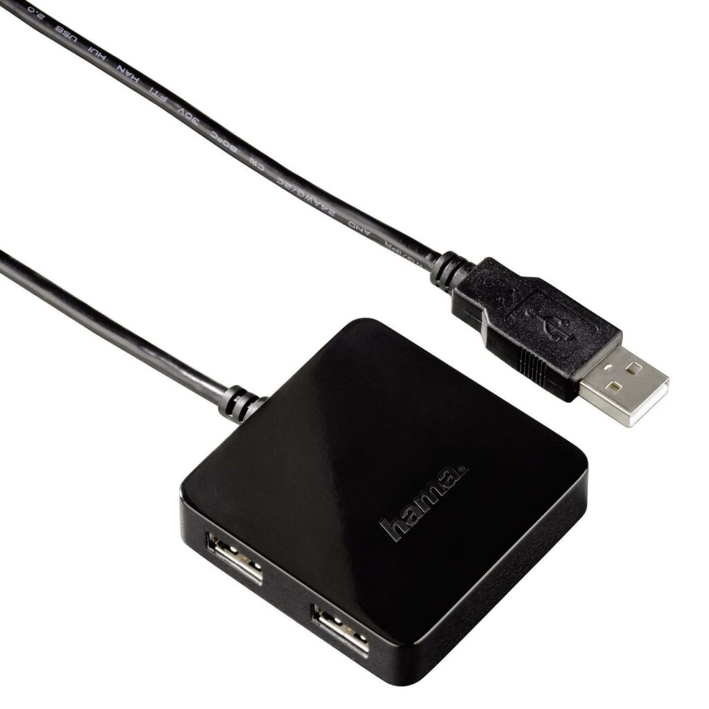
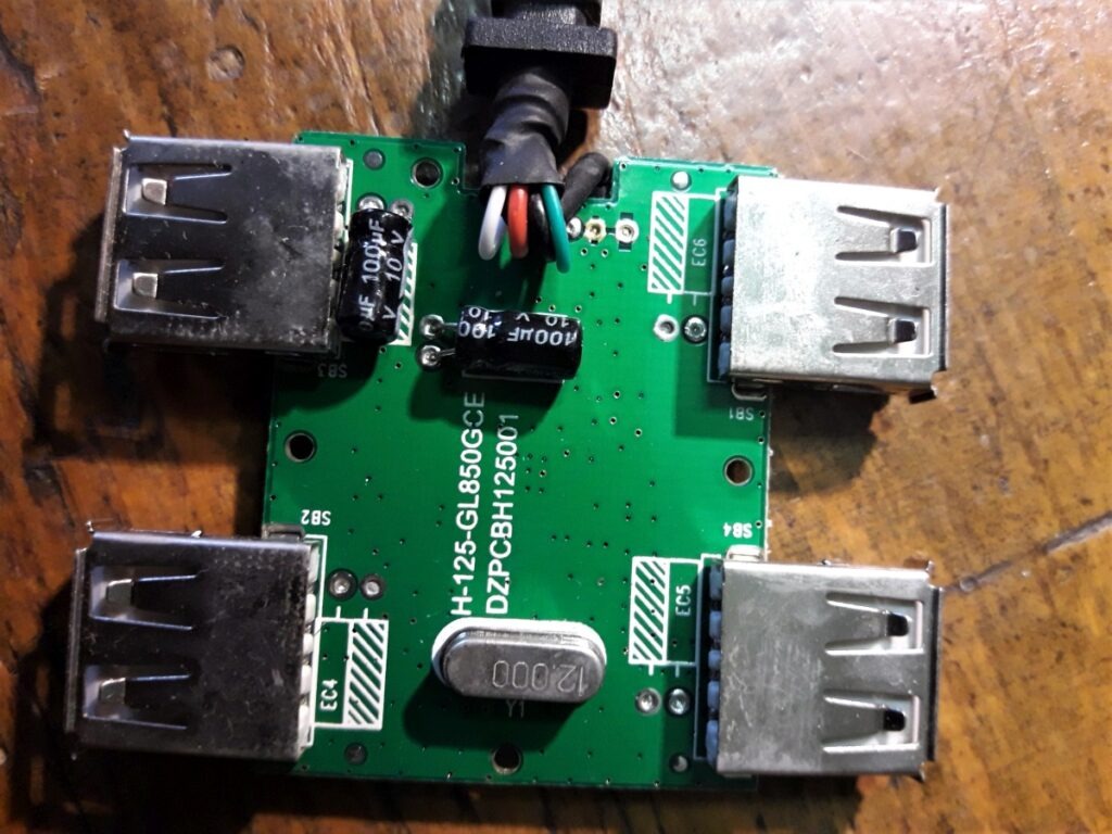
The wiring diagram is basically the same as in the second part, so I will not describe it here. You may be wondering what the difference is. The answer is simple. You don't need to look for a box. You can use the one from the USB hub. It worked for me 4-port USB hub from manufacturer Hama. It has enough space for audio circuits after soldering out one USB connector (Figure 1). Boiling requires a bit of skill. Two carpet knives worked well for me because they are both quite thin and quite strong. We carefully insert one into the gap between the cover and the base, and slowly and gently pry with the other, we expand the gap around the perimeter until all the latches are released. The cover should come off by itself (Figure 2). We fly out one USB connector for you - a plate from a USB sound card is fixed in its place. We fly for a short time at a temperature of 180-200 °C.
We choose the same model of USB sound card as in the previous part, any card from a Chinese store will do. We remove the cover much easier (Image 3).
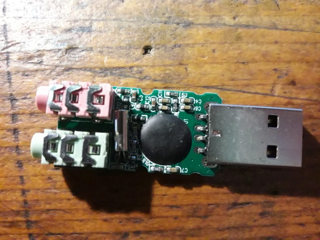
From the card, we fly out the USB male connector and two jack connectors for microphone and headphones. I would like to warn again to be careful when soldering, there is a risk of burning the PCB or tearing off the tracks with connections. We will connect the flown contacts of the USB connectors with flexible wires. We will determine their length when attaching the USB sound card to the USB hub. The boards should fit into each other, take up as little space as possible, and above all, their components must not touch each other to avoid damage. Probably no one wants to fly back SMD capacitor. When the boards are fitted, the wires measured and cut to the correct length, we can solder them. We will check if the boards fit into the box so that they do not stick out.
Next, we will bring the audio paths to the TCVR. We will achieve this through a 6-pin DATA connector. We will choose a long shielded audio cable. With one conductor for audio input, the second for audio output, and the third for grounding. We will connect the wires on the connector side with pins DATA IN, DATA OUT, and GND. We will thread the cable through the hole after the flown USB connector from the USB hub. We can also push a strip of plastic film onto the cable from the outside and inside of the box to ensure the hole is well closed.
DATA OUT 1200bps we solder through a 1k2 Ω resistor to the microphone input. It doesn't matter which channel we choose because the microphone has them connected.
DATA IN we first connect through a 3k3 Ω resistor to the speaker output (either right or left). Finally, we connect DATA IN through a 100 Ω resistor to GND.
Finally, we connect the TCVR GND to the USB sound card GND. We will adjust the position of the resistors to take up as little space as possible. We use bushings to prevent short circuits.
I recommend trying the connection without a cover first to correct any deficiencies.
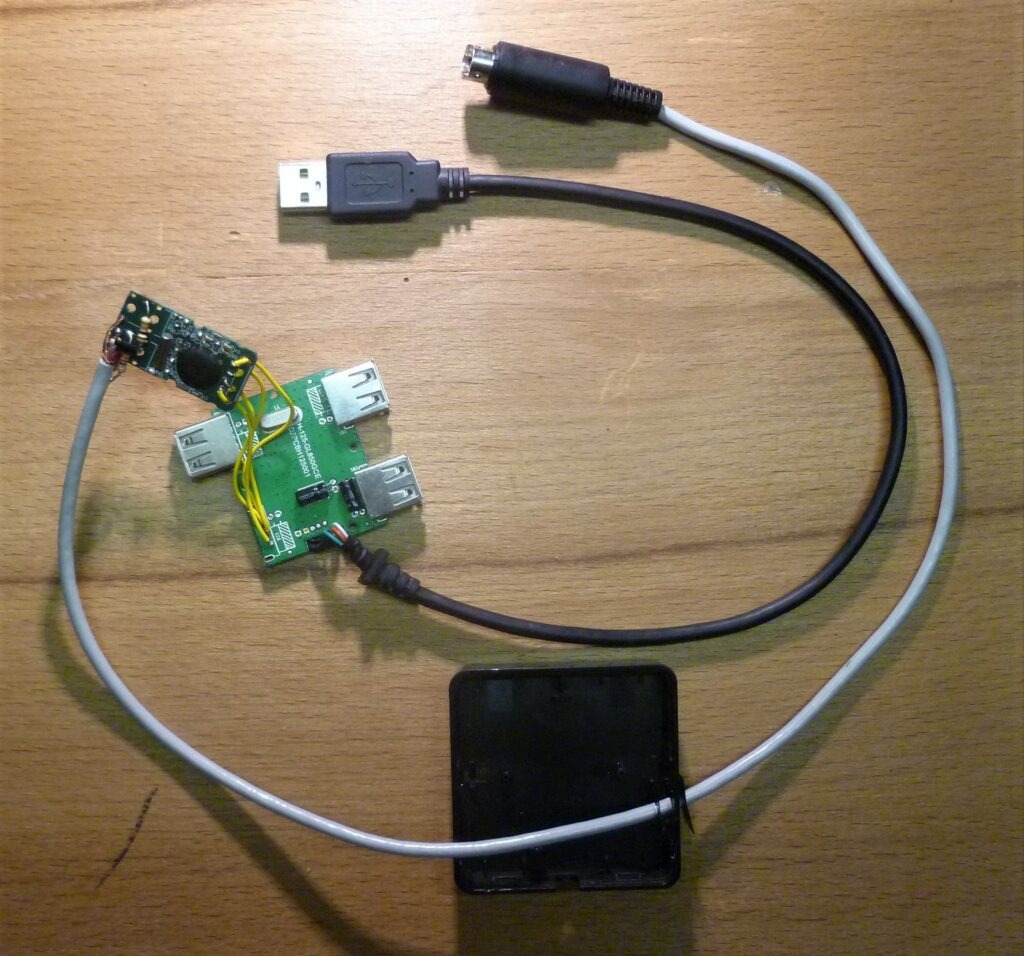
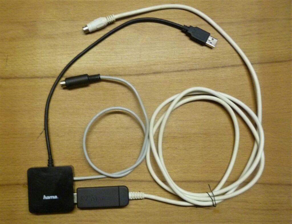
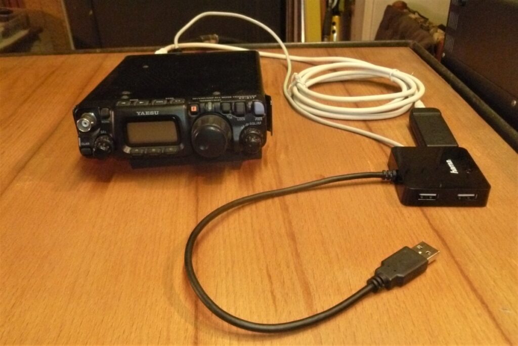
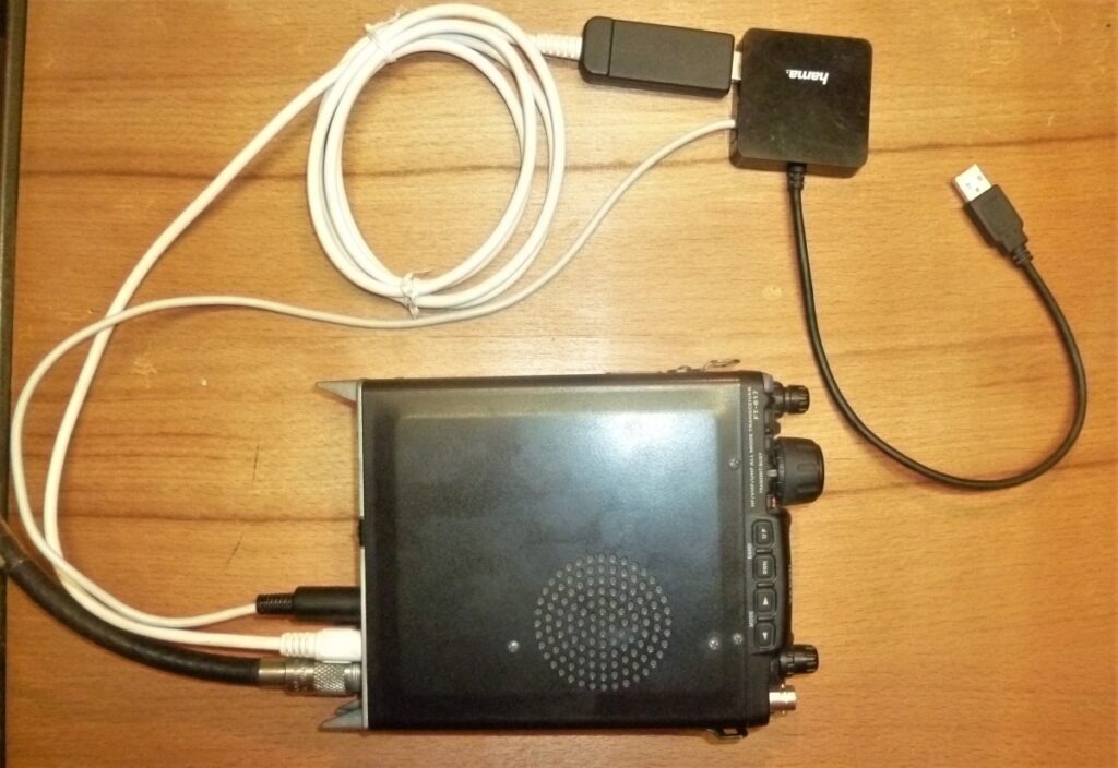
When everything works, we can close the box. We are done. Enjoy broadcasting.
Instructions for setting up software for digimodes
How to set up the Windows 10 operating system and program WSJT-x is located in this video:
Resources
How to control CW via computer
Martin Jánoš, OM1MJ