
Máte v hamshacku analógový merač výkonu a PSV with a hand? It is reliable, but it is sometimes difficult to get an accurate reading when tuning the antenna. Chris, SP2KMO, preto navrhol DigiMeter32. A digital reading on a color display is added to the reflectometer with diode detectors for the range 1.8-200 MHz.
The best part is that the hand continues to work without change. The electronics only "listens" to the detectors through a balancing amplifier with a large input impedance.
You will read in the article
What you will see on the display
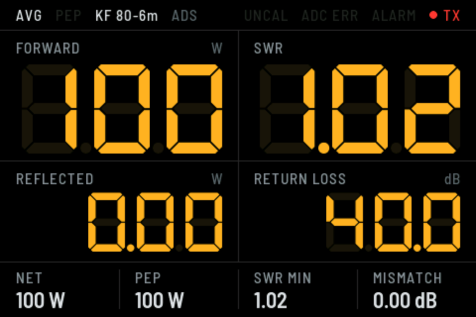
On the 4″ display with a resolution of 480×320 there are four large seven-segment data: FORWARD (Forward power), SWR, REFLECTED (Reflected power) and RETURN LOSS in dB. Unilluminated segments are faintly visible in the background, just like on the LCD of the measuring device.
The bottom bar shows the power to the antenna (NET), the second from the PEP or AVG data, the mismatch loss (MISMATCH) and the SWR MIN. This is the lowest PSV during the current broadcast, which comes in handy when tuning the antenna. The top bar reports UNCAL, ADC ERR, ALARM and TX statuses.
Hardware in two parts
The construction is divided into two parts. Part A is in the meter box near the coupler: the MCP6002 operational amplifier as a buffer, the ADS1115 16-bit converter and the X1 connector. The FWD and REF analog signals never leave the metal box.
Časť B is on the back of the display: converter Recom R-78E5.0-0.5, doska ESP32-WROOM-32D DevKit, LCD with ILI9488, ILI9486 or ST7796S controller, button, RGB LED and optional PSV alarm with buzzer. Both parts are connected by a five-core shielded cable with +13.8 V, +3.3 V power supply, I²C bus (SDA, SCL) and ground. The shielding is grounded only on the meter side. All components are outlet (THT) or ready-made modules.
Signal path
The voltage from the detector goes through a 1 MΩ / 318 kΩ (÷4.14) divider and filters to the tracker with the MCP6002 and from there to the ADS1115. The author chose the divider according to the measurement: at 100 W, the detector gives about 8.9 V, which is about 2.15 V at the converter. The range ends at about 13 V at the detector, that is, at about 200 W. For another meter, he gives the formula R2 = 1 MΩ · 3 V / (U_max − 3 V).
Only the 1 MΩ resistor itself protects the input. The author omitted the external Schottky diodes on purpose, because their leakage current over 1 MΩ would cause a large error. The detector must give a positive voltage with respect to ground and must be measured with the switch of the meter in the SWR position.
The ADS1115 selects the gain for each channel separately, up to a range of ±0.256 V in steps of about 8 µV. Therefore, it will measure even a very small reflected voltage with a good PSV.
Firmware and repository
The whole project is on GitHub. Firmvér je napísaný pre ESP-IDF 5.5 s grafickou knižnicou LVGL 9, which will be downloaded automatically. In addition to ESP32, it also runs on ESP32-C6. Compilation is standard:
- idf.py set-target esp32 (or esp32c6),
- idf.py menuconfig, where you set the LCD controller, pins and divider values in the DigiMeter32 section,
- idf.py build Flash monitor.
The source codes are clearly divided: meas.c handles the measurement, calib.c the detector curve, ui.c the screen and console_cmds.c the console commands. The schematic in the docs folder is generated by a Python script with the schemdraw library and is also in A3 printable PDF format. The detailed instructions for the firmware are only in Polish.
Calibration through the console
The diode detector is non-linear. According to the author, ten times the power will give 4.3 times the voltage instead of the expected 3.2 times. Calibration is therefore multi-point.
The firmware has a built-in calibration from the author's measurements with IC-7000 a umelou záťažou a štyri profily: KF 80-6m, orientačný 160m and two empty. Those who want higher accuracy connect to the serial console (115200 b/s) and calibrate themselves:
- zero stores idle voltages without transmission,
- cal fwd 10 adds a point at a transmitted power of 10 W. You must transmit a carrier (FM, CW or AM without modulation, not SSB) into a 50 Ω load. 4 to 8 points are enough, of which at least one is for low performance,
- profile copy and cal scale transfer the curve to another band with a single known point,
- export lists all settings as backup commands.
You can also set the PSV alarm threshold (default 3.0), transmission detection threshold (0.5 W), peak hold time or smoothing via the console. With the stream command, you can send data in CSV format, for example, to a table.
Control and practice
A short press of the button switches AVG/PEP, a long press another calibration profile. AVG is a smoothed average, PEP maximum with hold and slow decay, suitable for SSB. The RGB LED glows green when ready, red when transmitting, and blue when the ADS1115 is missing. The firmware then tries to find the converter again every second.
The author's notes from the measurement are also interesting. From 80 to 6m, the sensitivity of the coupling element at 10W varied by only ±2%, so one curve is sufficient for KV. On 80m, however, the meter itself introduces about 1.6 PSV into the line, and on 160m more than 3, so the radio reduces power. This is a property of the coupling member of the tested meter, not a modification. At 160 m, the author recommends removing the meter from the line.
Summary
The DigiMeter32 is a nice example of how, with a few modules and an ESP32, you can give an analog PSV meter a modern digital reading while keeping its hand. Schematic, parts list and firmware are publicly available at SP2KMO repositories. If you have a suitable meter at home and feel like soldering, this is an ideal project for winter evenings.