

Today I want to introduce you to an antenna that has caught my attention for several reasons: its performance (OM9M – MS/EME, top station contesting equipment in OK), high gain, and simple construction with acceptable dimensions (the boom is only 4.1m!). No other antenna on 144 MHz has intrigued me like this one....
This article comes again from Zoli OM7AQ: most of our stations use antennas based on F9FT and PA0MS for work on VHF/UHF bands. Quads like GW4CQT or Cheng-Cheng, Cue Dee are rarely encountered, and antennas based on K1FO, DJ9BV, DL6WU, or the hybrid quad DL7KM are only occasionally seen. Antennas YU0B, W2NLY, W1JR, W6QKI, quagi W5UN, or the hybrid loop-yagi based on I3DLI are almost unknown. I would like to gradually introduce at least some of these antennas.
The DL7KM beam consists of two 10-element hybrid YAGI antennas arranged one above the other. They are powered together by a double quad element. According to literature, the double quad has a gain of 2dB compared to a half-wave dipole. DL7KM states that based on measurements, the entire antenna has a gain of 17dBd, a front-to-back ratio of 25dB, and an input impedance of around 60 ohms. The radiation angle in the horizontal plane is 30 degrees and in the vertical is 18. The DL7KM beam has a significant advantage over 2xYagi systems - no transformer or combiner element is needed. This eliminates losses, impedance matching issues, and difficulties in constructing a transformer and combiner element. Another advantage is the fact that the distance between the antennas is only 1.2m (this is reflected in the radiation pattern by the narrowing of the side lobes). prispôsobením a ťažkosti pri vlastnom vyhotovení transformačného a zlučovacieho člena. Ďalšou výhodu je aj fakt, že vzdialenosť medzi anténami je len 1,2m (vo vyžarovaciom diagrame sa to prejavuje zúžením vedľajších lalokov).

In this article, you will learn about
 Mechanical construction
The antenna construction according to DL7KM is shown in the picture. All passive elements are made of Al or AlMgSi with a diameter of 6mm. The frames are made from square profiles of AlMgSi 20x20mm. To ensure sufficient stability, supports made of the same material with a length of about 3m are used. The elements are electrically connected to the frame. The second picture shows two possible variants. The radiator (double quad element) is made of Cu with a diameter of 5mm or Al (AlMgSi) with a diameter of 6mm. The dimensions are shown in the next picture. The radiator made of copper wire needs to be protected against corrosion by painting. It is attached to the frame.insulated, preferably using clips made of Teflon or textile bakelite.
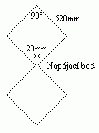 Power supply for the DL7KM antenna
According to the designer, we can power the antenna directly with 50 or 75-ohm coaxial cable with minimal matching error. The SWR in the range of 144 – 146 MHz should be between 1.4 and 1.7. If the SWR is higher, we can adjust the antenna's input impedance by shifting the radiator and the reflector walls towards the first directors. The antenna input is symmetrical, but powering with coaxial cable without a balun will only cause slight distortion in one side lobe in the horizontal plane. Other parameters (main radiation direction, gain, front-to-back ratio...) should remain unchanged.
Conclusion
The DL7KM antenna is advantageous to use instead of setups with two YAGI antennas, eliminating worries about matching. Additionally, the dimensions are very 'pleasant'.
| R1, 2, 3 | 1055 |
| D1 | 935 |
| D2 | 930 |
| D3 | 925 |
| D4 | 920 |
| D5 | 915 |
| D6 | 910 |
| D7 | 905 |
| D8 | 890 |
| a | mast |
| b | 4100 |
| c | 3000 |
| d | 1600 |
| e | 450 |