

Robert S53WW je skvelý konštruktér zariadení na VKV. Na jeho stránkach nájdete napríklad aj popis sústavy antén na 2m vhodnej do contestov a kvalitného transvertoru Javornik 144/14MHz. Poprosil som ho o súhlas na preklad a publikovanie týchto článkov. Robi mi ho obratom zaslal, za čo mu patrí veľké ďakujem. Postupne Vám ich všetky prinesieme na www.CQ.sk But if you don't want to wait, visit his website http://lea.hamradio.si/~s53ww/.
You will read in the article
Introduction
Po dôkladnej analýze rôznych predzosilňovačov pre môj nový 144/14 MHz transvertor I ended up staying with the Infeon BF998 MOS-FET. I had a very good experience with the old BF-981, so I started testing the BF998. This transistor is cheap, easily available and has very good characteristics. I didn't use GaAs FETs because they are hard to come by and expensive, and the differences are minimal.
It was clear from the analysis of the transverter that it determines the final resistance of the entire assembly preamplifier (ak využívate +17dBm zmiešavače s oscilátorovým signálom +20dBm a za ním zosilovač s IP3 out > 36dBm a zanedbávate odolnosť KV TCVR)! OK, commercial KV receivers should not have poor resistance (IP3 in < +15dBm to +25dBm, AOR-7030 to +30dBm). In this case, IP3 out should be at least at this level (+30dBm). The noise of KV receivers is at the level of 16dB, in the best case around 13dB.
If we estimate the loss in the ANT-XVRT coaxial cable to be about 0.5dB and require a resulting noise figure of around 2.2dB, we find that the XVRT gain must be at least 24dB (with a noise figure of 1dB). It follows that IP3 in must be more than +6dBm (=30dBm-24dB). It is not easy to meet this requirement precisely because of the preamplifier.
Low-noise preamplifier with parallel combination n times BF998
An attempt to fit the original preamplifier with a new BF998 did not bring significant improvement. He made a profit 26,5 dB, šumové číslo 0,8 dB, P1dB 17 dBm a IP3 in 0 dBm. Nie sú to zlé hodnoty, ale mohli byť aj lepšie.
Na prvom obrázku je bežné zapojenie predzosilňovača s dvojbázovým MOSFET s ohľadom na maximálny zisk. Idss sa nastavuje na minimálnu úroveň šumu (Idss je udávaný v rozsahu 2 až 18mA – zvyčajne býva medzi 10 až 15mA). Vstupná cievka L1 je vinutá na priemere 5mm 1,0mm AgCu drôtom; má 6 závitov s dĺžkou vinutia 11mm. Mala by byť umiestnená minimálne 2mm nad zemou a prinajmenšom 10 mm od kovových častí krabičky. Kapacitné trimre musia byť kvalitné. Diódy (Infineon BAR63-04 nebo BAR64-04 nebo BAR14-1) slúžia na ochranu MOSFET. Nemajú takmer žiadny vplyv na šumové číslo ani odolnosť, ich požitie v reálnych podmienkach je žiadúce. Najkritickejšou časťou je transformátor TR1: should be wound on a two-hole core of size A7 made of U17 material (Epcos, formerly Siemens&Matshushita). Materials from other manufacturers may be used with respect to gain degradation and P1dB. We wind two turns trifilarly - it is always better than an autotransformer with 6 turns (=2×3) of the primary winding and a branch on the second turn from the cold end (in practice, 4 turns are wound first, a branch is created by twisting the wires, and 2 more turns are wound). The TR1 leads must be shortened to 5mm and routed near the ground on the printed circuit board, otherwise oscillations at high frequencies may occur.
Pri experimentovaní som našiel zaujímavé zapojenie FET (používané v NF zosilňovačoch), kde paralelne spojené dva identické FET-y majú nižší šum ako jeden! Takže ak vyberiete ďalšiu BF998 (musí mať rovnaký Idss, nutné vybrať), môžete sa dostať až na hodnotu 0,6dB NF, zisku 26,5dB and the same or worse (!?) IP3 in. The problem with IP3 can be solved by adapting the output more appropriately - instead of a transformer with a ratio of 3:1, we will use a 2:1. In this way, we achieve +28.5dBm of IP3 power (P1dB is +19dBm). The general turn-on of the LNA n times BF998 is in the next picture (the achieved values are listed in the table).

Samozrejme som vyskúšal aj štvoricu BF998 (kto by nechcel) – šumové číslo sa zníži na 0,5dB, zisk ostáva 26,5dB (pri nastavení na minimálne šumové číslo) a IP3 out je +34dBm. To achieve this IP3 value, it is necessary to change the TR1 ratio to 1.3:1. Branch L1 is in the middle of the winding (on the third turn). At the first attempt, the amplifier oscillated above 3.5GHz, but this did not affect 2m. I tried placing a pair of transistors on each side of the PCB connected by short wires and separate G2 bias circuits (layout of components and blocking capacitor is critical). After this modification, the oscillation disappeared, but I would like to note that all connections are stable only under certain conditions. The layout of the parts is kritické, najmä sa to týka blokovacieho kondenzátora 1nF.
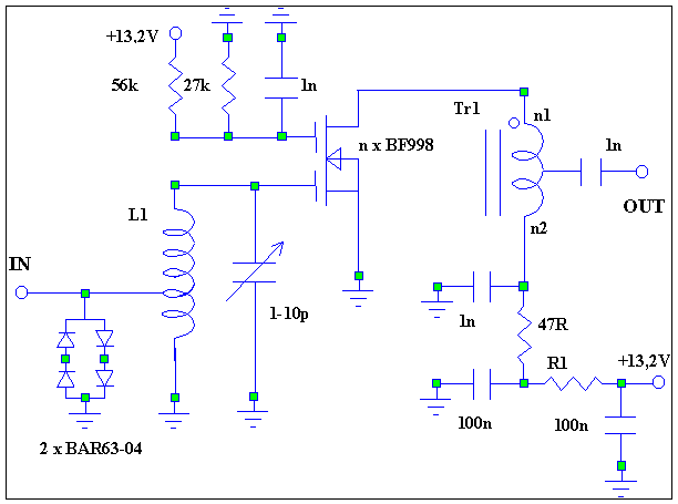

Circuit diagram of preamplifier n times BF998 (similar to single BF998). The values of the variable components can be found in the table. The adjustment of input and output is also different (see text). The material of the transformer is the same as in the previous case, when using several BF998 I recommend A4 size. We can tune the preamplifiers without measuring technology with a small trick to the minimum noise figure: we tune them to the maximum gain at 136 MHz (the noise figure hardly changes in a wide range).
You can download the circuit diagram here ftp://lea.hamradio.si/pub/vhfct/lnaa2.zip.
| n1 | n2 | R1 | NF [dB] | T [K] | G [dB] | IP3in [dBm] | P1db [dBm] | |
| 1 x BF998 | 4 | 2 | 150 | 0.8 | 61 | 26.5 | 0 | 17 |
| 2 x BF998 | 2 | 2 | 100 | 0.6 | 44 | 26.5 | 2 | 19 |
| 4 x BF998 | 1 | 3 | 10 | 0.5 | 36 | 26.5 | 7 | 23 |

Push-pull LNA with BF998
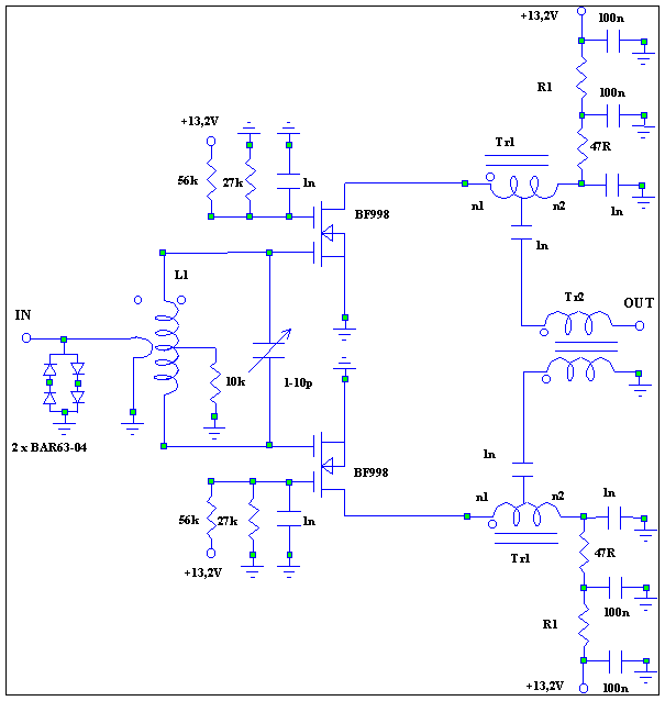
The push-pull amplifier is comparable in gain to a two-stage simple amplifier, and the IP3 is about 3dB better than the parallel design. So I tried to connect a pair of BF998 in push-pull. The first results were excellent: IP3 was +6 dBm (P1dB +23 dBm), but the noise figure was at least 1.3dB! After changing the input circuit, I achieved the noise figure 0,9-1,0dB, IP3 out 32,5dBm pri zisku 26,5dB (nastavenie na minimálne šumové číslo). Výsledné zapojenie je spojením dvoch jednostupňových zosilovačov podľa prvého obrázka.
Push-pull connection of two BF998. The input coil L1 is wound on a diameter of 11 mm with a wire of 1.0 mm AgCu; it has 4 turns and the winding length is 7mm. The coupling coil has 1 turn on the same diameter as L1 enameled Cu wire so that it cannot short out L1. Transformers TR1 and TR2 are on the same material as a simple LNA (size A7, material U17, Epcos). The output transformer TR2 has two bifilar windings.
Then I tried the push-pull connection of four BF998. The intention was to get IP3 in around +9dBm with a noise figure of about 0.8dB. Even though I achieved IP3 in as expected, it was not in my power to achieve the desired noise figure. This was still higher than 1.3dB, which I found inappropriate for the XVRT. However, this value may be suitable for other purposes, it still requires experimentation.
Notice:
Tieto predzosilňovače nie sú vhodné na priame pripojenie pred prijímač alebo transvertor pretože majú veľmi vysoký zisk. Ich efektívne využitie (aj keď ja neodporúčam používať predzosilňovače) je možné s útlmovým článkom na ich výstupe, čo zníži zisk. Vo väčšine prípadov 6-10dB zisku je dostatočné na preamplifier, ak skutočne musí byť použitý. S útlmovým článkom -20dB sa celkové šumové číslo zhorší z 0,5/0,6/0,8dB na 1,3/1,4/1,5dB. S útlmovým článkom -16dB sa celkové šumové číslo zhorší z 0,5/0,6/0,8dB na 0,8/0,9/1,1dB. Takže odporúčam Vám za predzosilňovačom používať Atenuátor -16dB (hodnoty pí-článku sú 68 ohmov voči zemi a 150 ohmov medzi nimi).
For high quality VHF and higher preamps, check out Dragan's YU1AW site: www.QSL.net/yu1aw/low_noise.htm.
By September 2002, I had built six preamplifiers with a noise figure of 0.5-0.6dB (BF998 Philips, labeled Mop) and three with a noise figure of 0.8-0.9dB (BF998 Infeon, labeled Mos). The bad news is that Epcos has stopped distributing U17 material and it is very hard to get U17/A4 dual hole cores. Their replacement is not yet known, but cores of a similar size made of material with a permeability between 20-30 are usable...
After measuring nine preamplifiers, I recommend a simple way to adjust the LNA 4xBF998 to minimum noise: tune the trimmer C to maximálny zisk, potom zvyšujte jeho kapacitu, kým zisk nepoklesne o 1dB! Naladenie nie je kritické, vstupný obvod je širokopásmový pri nastavovaní minimálneho NF (asi 10 MHz).
Robi, S53WW
http://lea.hamradio.si/~s53ww/
Translated and adapted with the permission of the author Viliam, OM3-0122
o šumu s vicero prvky má autor pravdu. Když ale začnete hledat prvek který nastavuje minimální šumové číslo, tak chybí. V čemž je odpověď co změnit. Ale i tak to bude chodit.