

I believe that many visitors to this portal have already read the description of Robi's high-resistance preamplifiers. S53WWRobi has agreed to translate all the articles that are on his website: http://lea.hamradio.si/~s53ww/Thank you!
In the article you will read
Introduction
Javornik 144/14 MHz je vyskoodolný transvertor at 144 MHz optimized for use with FT-1000MP as a 14 MHz station and a feeder loss of 0.5 dB between the antenna and the transverter input (without using additional preamplifiers!).
It has two (synchronous) RX converters with sufficient gain to overcome the noise figure of the FT-1000MP, which is 18 dB with IP0 turned on. It would be appropriate to slightly modify the FT-1000MP - to bring the SUB RX connector to the rear panel so that it does not disturb the appearance of the device.

The TX converter can handle an input level of the driver at 14 MHz in the range of -20 dBm to +20 dBm. The driver with the BFG196 transistor operates in class A and provides a very clean signal of +15 dBm, which is enough to drive the Mitsubishi hybrid M57727 (20W) or M57713 (10W).
RX converter

RX converter diagram, part one
RX converter diagram, part two


The total noise figure of the assembly (0.5 dB loss in the feeder + XVRT + IF RIG) is designed to be 2.0 dB (170K), which is better than required for TROPO at 144 MHz. 0.5 dB loss is represented by, for example, 33m of 7/8″ cable, 18m of 1/2″ cable or 11m of AircomPlus/H2000. Remember that investing in a good (read: thick) one is much better than investing the same amount in a preamplifier under the antenna! In cases where it is not possible to use a short feeder, the design includes a method for connecting a 4xBF998 preamplifier to the antenna connector (if the voltage is supplied via RX or RX/TX coaxial cable).
Table 1: technical parameters of the RX part of Javornik 144/14 MHz:
| JAVORNIK-144/14 | JAVORNIK-144/14 + FT-1000MP (IPO ON, MAIN RX) | |
| NF | 0.9dB | 1.5dB |
| G | 25.0 dB | – |
| IP3 input | + 4 dBm | – 2 dBm (@15 kHz, calculated, based on my measurement of IP3 at 14 MHz) |
The transverter gain is adjusted to a more appropriate level when using other types of RIGs (so that the overall dynamic range is as ideal as possible) by means of attenuators before the mixer. The following table shows the values of the pi-element resistors (R to ground/series R) for different RIG noise figures so that the overall noise figure is 1.5 dB.
Table 2: Pi-element resistor values before the mixer to achieve a total noise figure of 1.5 dB:
| G [dB] | NF [dB] | T [K] | IP3out [dBm] | ATT [dB] | PI ATT R values | IF RIG NF [dB] |
| 26.5 | 0.75 | 55 | 30 | 2.5 | 330/15 | 20 |
| 26.0 | 0.8 | 58 | 30 | 3.0 | 300/18 | 19 |
| 25.5 | 0.85 | 63 | 30 | 3.5 | 270/22 | 18 |
| 25.0 | 0.9 | 67 | 29 | 4.0 | 240/27 | 18 |
| 24.5 | 0.95 | 71 | 29 | 4.5 | 220/30 | 17 |
| 24.0 | 1.0 | 75 | 29 | 5.0 | 200/33 | 16 |
| 23.5 | 1.05 | 79 | 29 | 5.5 | 180/36 | 15 |
| 23.0 | 1.1 | 84 | 28 | 6.0 | 150/39 | 14 |
| 22.5 | 1.2 | 92 | 28 | 6.5 | 150/43 | 13 |
| 22.0 | 1.3 | 101 | 28 | 7.0 | 135/47 | 11 |
| 21.5 | 1.35 | 106 | 28 | 7.5 | 130/51 | 9 |
| 21.0 | 1.45 | 115 | 27 | 8.0 | 120/56 | 5 |
If the attenuation of the coaxial cable is greater than 0.5 dB, use the following formula to calculate the required XVRT gain at a desired NF of around 2.0 dB (T=170K):
TIF /G + TRX = T
T = 170 – 290*(10L/10 – 1)
Where TIF = 290*(10NF/10 – 1) and TRX is the profit function (G) according to Table 2.
For example: TIF = 11200 K (16 dB) and L = 0.8 dB ==> T = (170 – 58) = 111 ==> First we try with G = 446 (26.5 dB) and T RX = 55 K gives T = 80 which is too low so we try another value from Table 2 and calculate until we get to G = 281 (24.5 dB) and T RX = 71 K, which satisfies both conditions.
Finding the noise figure of an HF RIG is more complicated than it may seem. The data from the reviews by G3SJX and ARRL are based on sensitivity, G3SJX at 10 dB (S+N)/N on SSB (BW = 2.4 kHz) and ARRL at 0 dB S/N on CW (BW = 500 Hz). Assuming that the noise width is the same as the filter width (2400 or 500 Hz), anyone can easily calculate the noise figure (for example, for the ARRL data, NF = MDS – (-174 + 10LOG(BW))). But the width of the transmitted noise bandwidth is not the same, this fact is also visible when comparing the calculated noise figures according to the ARRL and G3SJX data. In Table 3, several calculated values of HF RIGs are given for comparison. The noise BW is clearly influenced by the IF circuits. I also want to say that the NF calculated from the G3SJX data are too optimistic, because the AF circuits narrow the BW and so some numbers are not detectable (IC-775, TS-870).
Table 3: NF values of various HF RIGs at 14 MHz with AIP on (Preamplifier OFF) calculated from G3SJX data and ARRL measurements assuming that the BW of the noise and IF filters is identical:
| HF RIG | NF [dB] according to G3SJX data (BW = 2.4 kHz) | NF [dB] according to ARRL data BW = 500 Hz) |
| FT-1000MP | 16 | 19 |
| FT-1000MP MARK-V | 17 | 20 |
| TS-870 | 18 | 18 |
| IC-775DSP | 12 | 9 |
| IC-756PRO | 12 | 13 |
| IC-738/736 | 12 | 14 |
Prečo 14 MHz medzifrekvencia a nie štandardná 28 MHz? Pretože linearita prijímačov HF RIG-ov je optimalizovaná pre 7 a 14 MHz. Na nižších pásmach je ju možné zlepšiť zaradením atenuátorov pri znížení citlivosti. Linearita na vyšších pásmach niektorých zariadení je zlá (bez akéhokoľvek dobrého technického vysvetlenia). Konkrétne linearita novších zariadení na 28 MHz je veľmi zlá (s výnimkou TS-870). Tabuľka 4 dáva odpoveď, ako je to IP3 rozličných HF zariadení.
Table 4: IP3 values of various HF RIGs at 14 and 28 MHz with AIP ON (preamplifier OFF) as reported by G3SJX (signal spacing 50 kHz):
| HF RIG | IP3 [dBm] @ 14 MHz | IP3 [dBm] @ 28 MHz |
| FT-1000MP | 24 | 6 |
| FT-1000MP MARK-V | 24 | 2 |
| TS-870 | 17 | 20 |
| TS-850 | 25 | 16 |
| IC-775DSP | 12 | 1 |
| IC-756PRO | 13 | 14 |
| IC-738/736 | 21 | 22 |
Now let's compare the VHF workstation setups with 0.5 decibel coaxial loss, XVRT and HF RIG using the Javornik 144/14 and LT2S. The LT2S is recognized as a good "standard" transverter with a gain of 20 dB, a noise figure of 1.0 dB and an IP3out of +27 dBm. Table 5 shows the NF and IP3in data when using the Javornik 144/14 and LT2S with various HF devices (the NF and IP3 data are from tables 3 and 4). Since the LT2S has too much gain for some HF devices, the overall sensitivity will be too low (depending on the antenna noise, which varies geographically). The data in parentheses is for the Javornik 144/14 with the gain set to match the NF of the LT2S. The data for Javornik 144/14 is in a separate column. By careful comparison, it can be seen that the gain and NF XVRT have an impact on the overall RX value of the system.
For example, let's take the FT-1000MP with LT2S: it may seem that the sensitivity will be weak and so we would immediately add a preamplifier with a gain of 10 dB to the antenna. The linearity in this case will deteriorate by 10 dB (IP3in = -23 dBm) even if the preamplifier is perfectly linear. Alternatively, the preamplifier will be turned on on the FT-1000MP (IP0 is OFF) - in this case the IF NF will drop from 18 dB to 8 dB and the total NF from 3.2 dB to 1.7 dB. But! IP3 will also drop from +6 dBm to -1 dBm and the total linearity will drop to about -20 dBm! Finally, it can be concluded that the LT2S can only be used with HF devices whose NF is 10-14 dB and IP3 values are some +20 dBm (at 28 MHz!!!).
Table 5: NF and IP3 values when using Javornik 144/14 at 14 MHz and LT2S at 28 MHz:
| HF RIG
| JAVORNIK-144/14 | LT2S | |||
| NF [dB] | IP3 [dBm] | G [dB] | NF [dB] | IP3 [dBm] | |
| FT-1000MP | 2.0 (3.2) | -2 (+2) | 25 (21) | 3.2 | -13 |
| TS-870 | 2.0 (3.2) | -8 (-4) | 25 (21) | 3.2 | + 0 |
| TS-850 | 2.0 (2.7) | + 0 (+2) | 24 (21) | 2.7 | -4 |
| IC-775DSP | 2.0 (1.8) | -9 (-10) | 22 (23) | 1.8 | -18 |
| IC-756PRO | 2.0 (2.1) | -9 (-9) | 22.5 (22) | 2.1 | - 6 |
| IC-738/736 | 2.0 (2.2) | -2 (-1) | 22.5 (21.5) | 2.2 | +1 |
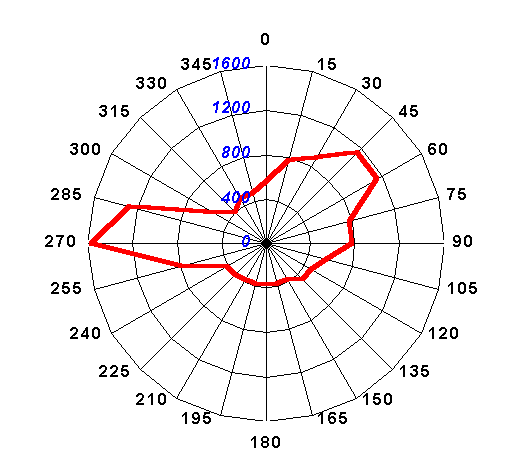 When considering the required sensitivity at 144 MHz in contests, we must also take into account the antenna thermal noise (TA). Some sources give a minimum of TA at 144 MHz 200K, if the antenna is pointed at a cold area of the sky. The reality is always a little worse. You can see in the picture TA at our contest site JN75DS, 1269 m asl when measured on 2.7.1999 at 19.00 LT. The lowest measured value was 370K, which is equivalent to 3.5 dB NF. The maximum values are in the direction of the town of Postojna (roughly 10 km, 500m asl) 1600K = 8.1 dB and the towns of Cerknica/Ljubjana.
It is known that if the RX system noise is equal to the antenna noise, then the S/N degradation is 3 dB. It is debatable what S/N degradation is acceptable for VHF contesting. I think that TRX should be 0.6 times the value of TAmin – gives a 2 dB S/N degradation. ATAmin is taken as 300/2 + 200/2 = 250K (half the ground noise and half the sky noise). In the case of a 2.0 dB (170K) AF system, we have sufficient margin for unpredictable losses in relé, prepojkách a podobne.
Local oscillators
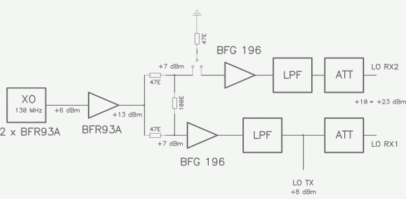
Oscillator diagram, part one
Oscillator diagram, part two
T/R switching diagram
XVRT connection diagram


Lokálne oscilátory (130 MHz) are connected according to Buttler with low-noise transistors BFR93a. The connection has two separate oscillators for two RX mixers. The maximum excitation level from the LO should be 23 dBm, which we set with attenuators in front of the mixers. It is possible to use different mixers (I recommend TUF-1H). When using a 23 dBm mixer (e.g. RAY-1 or SAY-1), it is possible to achieve an increase in the IP3 value by 1 or 2 dB (of the RX converter itself, because IP3 is determined by the IF RIG to be lower than +25 dBm). However, it is not harmful to use RAY-1 at the same excitation as TUF-1H (+14 dBm) - it is better to use SAY-1 than for +20 dBm P1dB. However, the price of a +23 dBm LO mixer is not worth the 1-2 dB improvement in IP3.
If you are not interested in both RX converters, then you only need to build one part.
TX converter
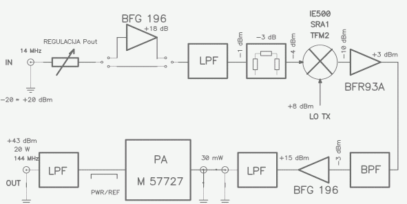
TX converter diagram, part one
TX converter diagram, part two
PA TX converter diagram


The TX converter can process a 14 MHz excitation signal in levels from -20 dBm to +20 dBm. For TRX, which has a very low signal level (-10 to -20 dBm), an amplification stage can be included. A low-noise broadband amplifier is included after the low-level mixer. The excitation operates in class A with BFG196 and provides a very clean signal of +15 dBm (IMD5 is around -60 dBc). For the final stage, it is most effective to use a trouble-free hybrid PA from Mitsubishi M57727 (20W) or M57713 (10W). This is not the best technical solution, since the modules are not the most linear, but at a power of 20/10W or less it is easy to achieve suppression of higher IMD products by more than 120 dB below the carrier level (which is enough to not sputter nearby stations).
The biggest problem of the entire TX part is broadband noise. There are two sources that contribute to its production: XVRT and HF RIG. Measuring Javornik 144/14 MHz at 20W output power, the value was -118 dBc/2.4 kHz and it can be further improved by 10-15 dB by using a TX mixer with a higher oscillator level (beware – TX noise will be only -108 dBc/2.4 kHz at 2W output power!). However, the noise spectrum of the HF RIG is much worse! Looking at the data from G3SJX (ARRL measures TX noise only at a distance of up to 20 kHz, which can only be considered phase noise, not broadband TX noise), it can be seen that none of the modern RIGs has broadband TX noise better than -110 dBc/2.4 kHz at a distance of 200 kHz from the carrier frequency. In a narrower range it is around 100 dBc/2.4 kHz, which is still not the value of the prevailing phase noise. This means that the S/N ratio of the transmitted signal is only 100 -110 dB!!! Two 500W VHF stations with 16 dBi antennas at a distance of 100 km (!) with radio visibility will produce a signal of -27 dBm – which is 111 dB above the SSB noise level (I take the sensitivity to be -138 dBm). Just pressing the PTT on a device with a transmitted noise level of -111 dBc/2.4 kHz will mean an increase in noise by 3 dB at the other station!
One might argue that wideband TX noise is especially a problem during VHF contests in more crowded areas. For example, in S5 the average distance between well-equipped stations is 50 km and distances of 10-20 km are not unusual!
Connecting JAVORNIK 144/14 and FT-1000MP
To fully utilize the capabilities of the FT-1000MP with its two separate RX inputs, we will need a simple circuit to connect the XVRT and IF RIG. A 14 MHz crossover switch can be considered the minimum, which in one position connects both RX converters to the MAIN RX input. This is because the SUB RX is not of the same quality as the MAIN RX and does not provide DSP. However, I estimate that I will only switch from SUB to MAIN RX in 20% of the connections.
The interface may also include a circuit that will allow the S&P system to operate on SUB RX with both RX converters independently of a switch with high-quality NB, crystal filters, etc.
Further developments
This concerns the problem of transmitted broadband noise. One option is to build a high-quality VFO at 130 MHz (preferably VXO or DDS/PLL) and use a HF RIG at a single frequency. In this case, a 14 MHz crystal filter could be placed between the RIG and the XVRT. This would result in a better S/N ratio of the transmitted signal and a lower level of IMD products at the receiver.
Robi, S53WW
Slovak translation by Viliam, OM3-0122