
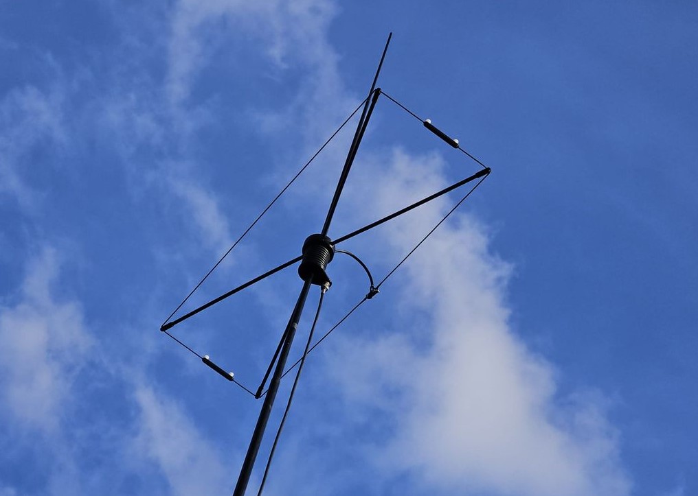
During amateur radio operation in the field, we often solve the same problem. We want to use a directional antenna, which will give us better properties than an ordinary vertical antenna, but at the same time we need it to be easily carried in a backpack. Classic multi-element yagi nemusí byť vždy najpraktickejším riešením. Práve tu prichádza na rad Moxon.
It is a two-element directional antenna that uses a radiator and a reflector. Both elements have characteristic curved ends pointing towards each other, creating a compact rectangular shape. The construction is simple, does not require complex phasing wiring and allows direct feeding with a coaxial cable with an impedance of 50 ohms.
Zaujímavú prenosnú verziu pre dvojmetrové pásmo predstavil rádioamatér OE5JFE. Its construction uses fiberglass rods and 3D printed connecting parts. He followed up on this project PE1RWL, ktorý pripravil vlastnú upravenú verziu s označením 2 meter Moxon antenna. The use of 3D printing in the mechanical design of the antenna is especially interesting on it.
You will read in the article
Construction designed for a backpack
Hlavnou myšlienkou projektu je vytvoriť ľahkú a skladnú smerovú anténu, which can be quickly assembled directly on site. Such a solution is suitable primarily for SOTA a GMA aktivácie, poľné dni alebo VHF contests from mountain stations. Instead of carrying a bulky antenna, we have several fiberglass rods, wires and small plastic components in our backpack.

3D printed parts ensure the connection of individual parts and at the same time enable repeated assembly and disassembly. The advantage is that there is no need to make complicated metal brackets or use large supporting structures.
The OE5JFE project uses a central connecting part, a BNC connector holder, four end caps, two spacers and a power point protection part. PE1RWL has prepared a modified set of STL files consisting of a Mobile Moxon Heart central part, a Feedpoint, two spacers and four End Buttons.
Necessary components and material

In the implementation according to the PE1RWL design, in addition to 3D printed parts, we will also need several commonly available components:
- 4× fiberglass rod with a diameter of 7.9 mm and a length of 360 mm,
- 1× panel BNC connector,
- approximately 160 cm of RG58 coaxial cable (I would recommend Aircell5),
- 5 cm of shrink tubing,
- 2× screw M4 × 12 mm, 4× washer M4 and 2× nut M4,
- 2x cable eyelet M4 for a conductor with a cross-section of 0.5 mm²,
- 2x conductor for the radiator with a length of 44 cm,
- 1× conductor for a reflector with a length of 96 cm,
- 4× M4 x 10 mm plastic screw for spacers.
The stated dimensions of the conductors are the result of tuning a specific design. Therefore, PE1RWL recommends leaving a certain reserve during the initial assembly and adjusting the final dimensions only after measuring with an antenna analyzer.
PLA material, layer 0.2 mm and filling 15% was used for 3D printing of PE1RWL files. When printing, it is necessary to observe the dimensions of the openings for fiberglass rods and individual connecting elements.
Mechanical assembly and power point
The basis of the entire structure are four fiberglass rods that create the rectangular geometry of the antenna. Their connection is ensured by a central 3D printed part and end caps. Two spacers maintain the correct distance between the emitter and the reflector.

The power point deserves special attention. The radiator wires are connected using cable lugs and screw connections. The RG58 coaxial cable (I recommend Aircell5) is connected to the panel BNC connector. Soldered places and wire transitions must be mechanically relieved so that they are not damaged when folding and unfolding the antenna.
The protection of the power supply point was one of the modifications of the original OE5JFE design. The author added a separate protective part that stabilizes the sensitive connection of the coaxial cable with the antenna wire. After the soldering is completed and successfully checked by the analyzer, he recommends mechanically securing the joint with a suitable adhesive or epoxy resin.
Calculation of dimensions and antenna tuning
When building Moxon, it is important to correctly determine the dimensions of both elements. It is not enough to just use the approximate length of a half-wave dipole and bend its ends. The resulting impedance and directional properties are affected by the entire geometry, including the distance between the elements and the gaps between their bent ends.
Both authors used an online tool for the proposal Moxon Rectangle Generator. This allows you to calculate the dimensions of the antenna according to the required working frequency and the diameter of the conductor. For the 144 MHz band, it is therefore advisable to start with a calculation for the selected middle working frequency and then verify the dimensions by measurement.
The mechanical assembly is followed by a check using an antenna analyzer. We mainly monitor resonance frequency, impedance and PSV. If the PSV minimum is outside the required part of the band, we adjust the length of the wires. When tuning, it is advisable to change the dimensions gradually and repeat the measurement after each adjustment.
Installation and use in the field
One of the most interesting features of this construction is the possibility of quick disassembly and assembly. After disassembly, the individual parts do not take up much space, and the entire antenna can be conveniently stored in a backpack. It is enough to assemble it at the site, connect the coaxial cable and fasten it to a suitable pole or telescopic fiberglass pole.
Polarization must also be considered during assembly. The original design of the OE5JFE provides for the possibility of fixing the antenna in both vertical and horizontal positions. For this purpose, mounting holes are prepared for both orientations. When choosing a support rod for vertical polarization, it is important to use fiberglass or other non-conductive material, not a carbon rod, which could affect the electrical properties of the antenna.
In the following video, you can see the construction and practical implementation of the moxon antenna from solid parts:
Another video completes the presentation of the structure and its practical use:
Conclusion
The Moxon PE1RWL is a nice example of how 3D printing can simplify the construction of a ham radio antenna. Instead of complicated mechanical joints, we get a set of purpose-built plastic parts that allow quick assembly and repeated assembly.
In combination with fiberglass rods and a simple wire design, an interesting directional antenna for the two-meter band is created. Its greatest benefit is not an attempt to compete with large VHF antenna systems, but to offer a practical solution for the radio amateur who wants to go out into the field with minimal load and does not want to be dependent only on an omnidirectional antenna.
STL files and construction details can be found at Thingiverse – 2 meter Moxon antenna by PE1RWL. The original design of OE5JFE is available at Thingiverse – VHF 2m band Moxon beam antenna.