
The current boom in amateur radio satellites operating in low Earth orbit (LEO) brings new opportunities, but also technical challenges, to operators. Whether it is classic FM repeaters on the SO-50 and AO-91 satellites, links on the International Space Station ISS, or advanced digital operation, the success of establishing a stable QSO depends primarily on the antenna system. When working through orbital repeaters with conventional linearly polarized antennas, operators in their Shack constantly encounter deep signal leakage - a phenomenon known as QSB. This adverse phenomenon, exacerbated by Faraday rotation in the ionosphere and the constant change in the position of the rotating satellite, is effectively solved by circular polarization.
However, the production of industrial cross-directional antennas is mechanically demanding and financially expensive. In the spirit of open sharing of hardware and licenses GNU GPL v3 však vznikol prepracovaný open-source koncept od nemeckého rádioamatéra DB6KT (publikovaný na platforme Thingiverse under number 4323183), which combines precision RF engineering with 3D printing technology. This project allows you to build an ultra-lightweight cross yagi anténu pre pásma 2m a 70cm s kruhovou polarizáciou.
In the article you will read
What are the advantages of circular polarization for VHF satellite operation?
Pri bežnej terestriálnej prevádzke na veľmi krátkych vlnách striktne dodržiavame polarizáciu podľa druhu prevádzky. Pre FM prevádzače, digitálne siete DMR, D-Star či paketovú sieť APRS je nepísanou normou vertikálna polarizácia. Naopak, pri diaľkových spojeniach prostredníctvom odrazov From meteoritických stôp (meteor scatter), v móde EME (Zem-Mesiac-Zem) alebo počas rádioamatérskych contestov v režimoch SSB, CW a RTTY sa uplatňuje polarizácia horizontálna. Satelitná prevádzka však vyžaduje úplne odlišný prístup.

Satellites orbiting in low orbits constantly change their spatial orientation relative to the receiving QTH of the operator. When the linearly polarized signal from the satellite antenna passes through the ionospheric layers, it is twisted. If the earth station uses a fixed vertical or horizontal antenna, at moments of polarization mismatch, a loss occurs, which at its maximum reaches 20 dB. The result is a rapid decrease in the signal-to-noise ratio (SNR), constant fluctuations of the automatic gain control (AGC) circuits, leaks to the noise floor and, in the worst case, a complete loss of readability of the session and a forced exit to the QRT state.
Circular polarization – right-handed (RHCP) or left-handed (LHCP) – completely eliminates this problem. The electromagnetic field rotates 360 degrees during each wave period, allowing the antenna to receive a linear signal in any position with a constant attenuation of only 3 dB. If both sides of the line have the same circular polarization, the polarization loss drops to zero. Cross-directional antennas are used to implement this principle, where two sets of elements are mechanically rotated by 90 degrees on a common carrier (boom) and electrically fed with a phase shift of 90 degrees using a phase-shifting coaxial line or a matching transformer.
Pri cross-band prevádzke, kedy sa využíva split frekvencia (typicky Uplink na 144 MHz a Downlink na 430 MHz), je kľúčové zamedziť vzájomnému ovplyvňovaniu oboch vetiev. Silný vysielací výkon (QRO) by mohol zahltiť citlivé vstupné obvody prijímača a spôsobiť intermodulačné skreslenie (IMD). Z toho dôvodu sa do cesty zaraďujú selektívne filtre typu LPF (dolná priepust) pre vysielaciu vetvu a HPF (high pass) for the receive branch, most often integrated in a combined miniduplexer. This ensures that modern ADC prevodníky a digitálne signálové procesory (DSP) v architektúre SDR TCVR they operate without overload, which allows for clear reception even with weak signals at the noise floor.
3D printed construction details according to DB6KT
Construction presented by radio amateurs DB6KT under Thingiverse reference #4323183 brings an innovative perspective on the mechanical construction of cross-directional antennas. Traditional heavy metal element mounts are completely replaced by precise, modular plastic holders manufactured using the additive method. The main advantage of the project is the minimization of the total weight while maintaining the high torsional strength of the entire system.
As a central support (boom), the author proposed to use a common fishing rod made of fiberglass. Fiberglass is an ideal material because it is completely non-conductive and radio transparent, so it does not deform the antenna radiation pattern and does not introduce parasitic capacitances into the system. For stationary installations, the author updated the project with mounts adapted for common plastic pipes with an outer diameter of 25 mm. The selection of materials for the elements themselves is optimized for maximum electrical conductivity and easy mechanical processing at home:
The passive elements (reflector and individual directors) are made of 3.2 mm diameter aluminum alloy welding wires. This material is characterized by low weight, low price and excellent resistance to oxidation.
The active radiators are made of 4.0 mm diameter brass tube. The choice of brass is strategic – unlike aluminum, it solders excellently, which allows for direct and reliable connection of the power coaxial cable or phasing line without transition resistances.
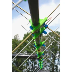
3D printed brackets precisely fix the elements at right angles while providing the necessary mechanical displacement along the frame axis for correct phasing of the circular polarization. DB6KT designed optimized geometries for two separate antenna arrays, the mechanical parameters of which are summarized in the following table:
| Frequency band | Number of elements | Passive element material | Emitter material | Boom length | Total weight of the assembly |
|---|---|---|---|---|---|
| 2m (144MHz) | 6 elements | Aluminum welding wire 3.2 mm | Brass tube 4.0 mm | approx. 2.0 m | less than 600 g |
| 70cm (430/440MHz) | 10 elements | Aluminum welding wire 3.2 mm | Brass tube 4.0 mm | approx. 2.0 m | less than 500 g |

From a 3D printing technology perspective, filament selection is crucial for the long-term mechanical integrity of the antenna outdoors. Conventional PLA is absolutely unsuitable as it degrades rapidly under UV light and loses stability at temperatures above 50 degrees Celsius. Structural elements exposed to weathering must be printed from PETG or, ideally, ASA. ASA filament offers excellent UV stability, high heat resistance and impact strength. When preparing to print in a slicer, it is recommended to set the layer thickness to 0.2 mm, use at least 3 to 4 peripheral walls and a fill density in the range of 35% to 50% with a gyroid spatial pattern that exhibits uniform strength in all three axes and prevents parts from cracking under wind stress.
User insights and practical operation
The practical deployment of DB6KT antennas in the amateur radio community has brought a lot of positive feedback. Users most appreciate the extreme lightness of the entire structure. The total weight of the 2-meter version is under 600 grams and the 70-centimeter version is under 500 grams, opening the door to portable satellite operation during portable activities.
Low weight and minimal moment of inertia are a huge advantage even for fixed installations on building roofs. For automatic tracking of LEO satellites it is not necessary to invest in massive and expensive industrial azimuth-elevation rotatorsUsers successfully build lightweight rotators powered by model-grade servos or microcontroller-controlled stepper motors Arduino Nano. Tento prístup je mimoriadne populárny v celosvetovej sieti otvorených pozemných staníc SatNOGS, kde antény DB6KT slúžia na automatizovaný zber telemetrie a dát z vedeckých aj rádioamatérskych CubeSatov.
The dimensional accuracy provided by additive manufacturing is fully demonstrated during the electrical life of the antenna. With strict adherence to the element lengths and their mutual spacing, the antenna exhibits excellent PSV (standing wave ratio) values directly after assembly. When measured using a vector antenna analyzer, the PSV values in the satellite segments 145.800–146.000 MHz and 435.000–438.000 MHz are stably below 1.5:1, which eliminates the need for complex mechanical tuning. This is also facilitated by the fact that the brass radiators allow direct soldering of the coaxial cable, which eliminates the use of heavy terminal blocks and minimizes parasitic inductances.
Summary
Combining amateur radio engineering with modern 3D printing brings a high degree of flexibility to the world of radio frequency technology. The 3D printed Yagi cross antenna project by DB6KT is a perfect example of how to make advanced concepts such as circular polarization accessible to the general community at a fraction of the commercial price. The minimal financial cost of the material (aluminum welding wires and brass tubes) combined with the mechanical properties of ASA filaments make this construction an ideal weekend project for any technical enthusiast looking for a reliable solution for working via amateur radio satellites.