
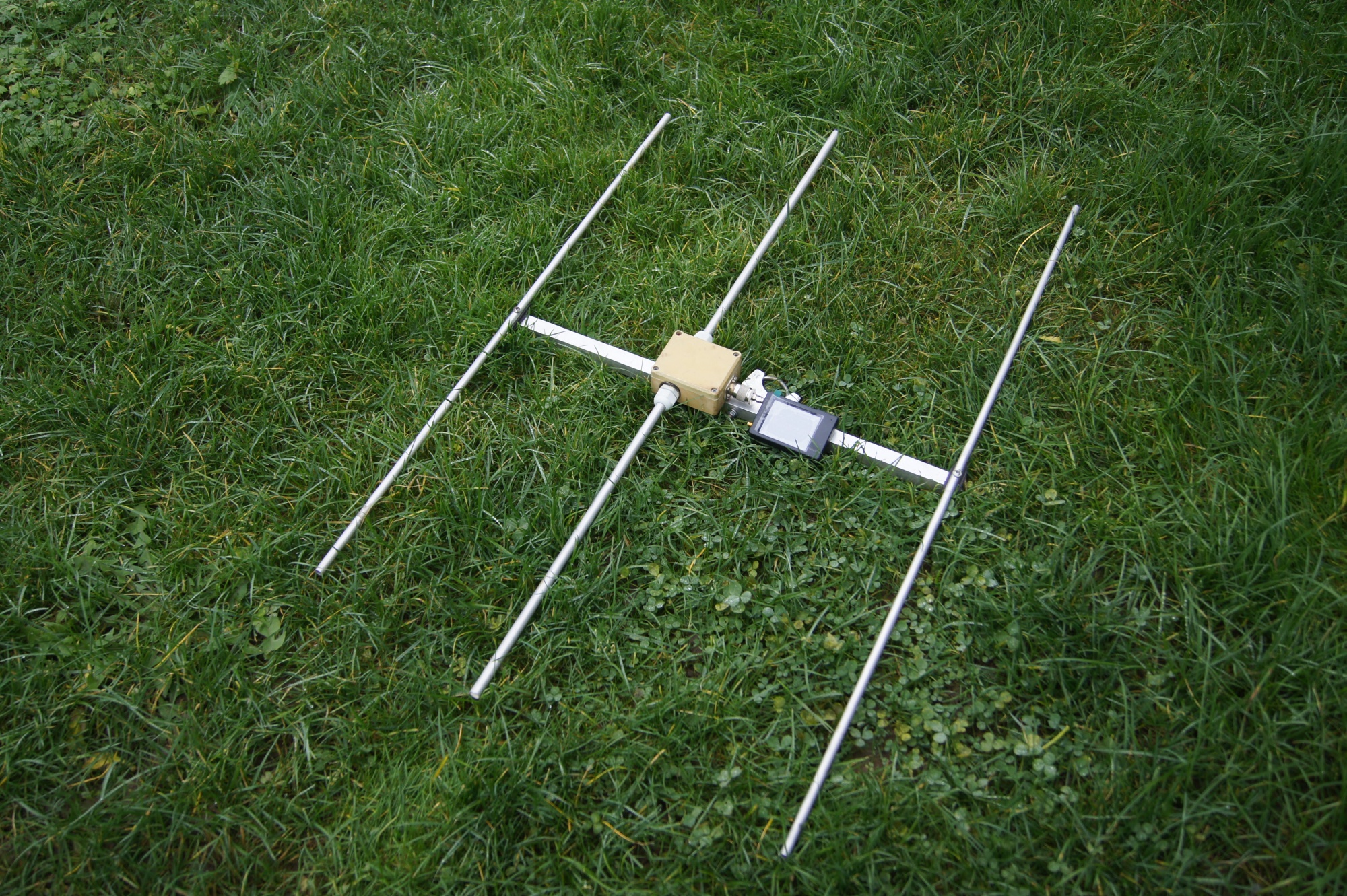
Are you looking for a non-critical 144-146 MHz high bandwidth directional antenna that you connect directly with 50 ohm coax? The construction of the German radio amateur Martin Steyer, DK7ZB, with a boom length of 60 cm (0.29 λ) represents a proven, simple and broadband solution for SOTA activations, portable operation and home use.
Unlike the 28 Ω impedance version (which requires a transformer from two parallel 75 ohm coax cables), this version is designed for a direct 50 ohm feed. It brings a higher tolerance to the surrounding environment, a wide band with low PSV and a simpler construction.
You will read in the article
Technical parameters and properties
According to the author DK7ZB, this 50-ohm design provides very stable parameters throughout the 144 to 146 MHz range:
| Parameter | Value |
|---|---|
| Input Impedance (Z) | 50 Ω (direct supply) |
| Work zone | 144,000 – 146,000 MHz |
| Boom length | 600mm (60cm) |
| Adaptation (SWR / ČSV) | Large bandwidth, non-critical design |
| Assembly of elements | Insulated above the boom (e.g. polyamide clips) |
Thanks to the wider impedance curve, this antenna also forgives minor manufacturing inaccuracies and the influence of nearby objects or adverse weather conditions during operation in the field. The simulation in MMANA looks like this:

Distances and positions of elements on the boom
The spacing between the elements is designed so that the total length of the boom reaches exactly 600 mm (60 cm). The beginning of the measurement (0 mm) starts at the position of the reflector.
| Boom section | Distance | Overall position from the reflector |
|---|---|---|
| Reflector - Radiant (REF-Rad) | 350 mm | 350 mm |
| Žiarič – Director (Rad-Dir) | 250 mm | 600 mm |
Exact lengths of the elements according to the diameter of the material
The lengths of the elements depend on the diameter of the material used (tubes or solid bars). All dimensions in the table allow for isolated assembly of the elements above the supporting boom using polyamide clamps.

| Element diameter | Reflector | Radiant (dipole) | Director |
|---|---|---|---|
| 10 mm | 1030 mm | 984mm (10mm) | 864 mm |
| 8 mm | 1032 mm | 984 mm | 874 mm |
| 6 mm | 1034 mm | 988 mm | 884 mm |
| 4 mm | 1036 mm | 993 mm | 897 mm |
| 3.2 mm | 1037 mm | 993mm (4mm) | 903 mm |
The radiator is designed as an uncoupled dipole. For the diameter of the radiator, a tube with a diameter of 10 mm is used as standard (or 4 mm for wire/thin versions).
50-ohm direct feed and current balun
Since the input impedance of the antenna is 50 Ω, no coaxial transformation section is used. A 50-ohm coaxial cable (eg low-loss Aircell-5) is connected directly to the emitter terminals.
In order to prevent the flow of high-frequency currents after the external braiding of the cable, it is necessary to create a high-frequency choke (choke balun) immediately at the power supply point:
Directly at the power point of the radiator, make 4 to 5 turns of power coaxial cable (e.g. Aircell-5) tightly wound with a diameter of about 50 to 60 mm and secure them with cable ties.
Mechanical construction and assembly
A square aluminum profile measuring 15 × 15 mm or 20 × 20 mm with a length of approximately 65 cm (with an overhang for attachment to the mast) will serve as a supporting boom.
The elements must be galvanically isolated from the boom. It is most suitable to use plastic polyamide clamps (DK7ZB clamps / Stauff clamps). If the elements are fixed directly through the boom without insulating pads, it would be necessary to take into account the correction of the length of the boom (Boom Correction Factor).
It is advisable to enclose the power supply point of the disconnected dipole in a small weather-resistant plastic box.
TIPS for portable antennas
If some parts of the antenna can be disassembled, wing nuts or nuts with a plastic head are more suitable instead of classic nuts. Screws with a plastic head are also suitable. The advantage is assembly without tools and they are more difficult to lose.
Vlado OK1VPZ filled the antenna box on his antennas with PUR foam. It fills the space and prevents moisture from entering critical parts (joints, adjustment circuits from coaxial cables, connections to the connector). This procedure also worked for me.
Antenna tuning procedure

Thanks to the 50-ohm concept, the antenna is extremely tolerant and, if the dimensions are precisely observed, it works immediately without complicated adjustments. After assembly, connect antenna analyzer or PSV meter.
If the resonant minimum is shifted outside the required section (144.200 MHz for SSB/CW or 145.500 MHz for FM), the length of both arms of the emitter is adjusted by symmetrical shortening or lengthening by a few millimeters.
Take the measurement in an open space at a height of at least 2 meters above the ground and far enough away from metal structures.
Field use (SOTA and Portable)
Thanks to its compact 60 cm boom and low weight, it is an ideal directional antenna for working from hills. The large bandwidth and resistance to detuning guarantee that the antenna will work reliably even when the weather changes, in damp or windy conditions.
During transport, the elements can be easily dismantled from the polyamide clips and packed together with the boom in a small case for the device.
Advantages of the 50-ohm version over the 28-ohm version
While the 28-ohm version provides slightly higher gain and a sharper front-to-back ratio (at the cost of having to use an adaptive transformátor 2×75 Ω paralelne), 50 ohm version of the DK7ZB yagi it wins in the category of simplicity and robustness.
It has no transformation losses on the matching line, eliminates the construction of the transformer member and the antenna exhibits a wider working band, making it an ideal first construction project for any radio amateur.
Medzi vlastnosti / výhody tohto typu antén s otvoreným dipólom a bez transformácie sa dá uviesť aj dvojpásmovosť. Anténa funguje aj v 70cm pásme, rezonuje, smeruje, ale vyžarovací diagram je „strapatý“ s troma doprednými maximami a menším ziskom (asi -2dB voči 2m). Používam 4 prvkovú „PVC“ verziu na „ruksakové“ kontestovanie https://www.qsl.net/dk7zb/PVC-Yagis/4-Ele-2m.htm . Nevýhodou tejto antény zase je nutnosť dodatočnej ochrany pred statikou, pre stabilné použitie, optimálne štvrť vlnným skratovaným vedením.
Pozor ale na prispôsobenie, na 70cm je PSV cca. 2,5: 1. Takže len v núdzi.
Pre dvojpásmovú prevádzku radšej siahnuť napríklad po 2+2 or 2+3 https://www.qsl.net/dk7zb/Duoband/duoband_2-70_2-3.htm
TIP – nitovacie matice so zapustenou hlavou ako https://www.bbtechnik.sk/nitovacie-matice/nitovacia-matica-m-4-ocel-zn-zapustena-ryhovana-pre-hrubku-materialu- 1-5-3-0mm/ Nápad pochádza od Petra OK1FIG a umožňuje elegantne vyriešiť výstupky na spodnej strane boom-u.
TIP – matice or skrutky s plastovou hlavou
Pre portablové použitie je praktické použiť matice or skrutky s plastovou hlavou, aby sa dali prvky v prípade potreby odobrať. Maticu s plastovou hlavou používam aj v krížovej platničke (pre úchyt na stožiar).