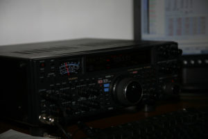
Measurement of SSB transmitter by two-tone generator
When using commercial equipment, we usually set the modulation level according to ALC. It's a good way, however, it is good to check the linearity of the whole transmission chain (TCVR + PA) using a two-tone test. In this way, we can detect the awakening in a relatively simple way, improperly set operating points, carrier or unwanted sideband penetration or feared vibration.
A frequent argument to the question: “You've already measured the linearity of your TCVR?” is the answer, that I don't have the necessary equipment for that. Error! How about that?

The nonlinearity of the output signal is affected by the NF modulation amplifier up to the HF output stage, that is, in many degrees. The output stage has the greatest influence on the resulting signal because it works with large levels of voltages and currents in a large part of the characteristics of the active element. The maximum allowable distortion should not be noticeable during oscilloscope inspection.
We will need: measured transmitter with source, artificial load (we can also use an antenna in an emergency – but we shouldn't), two-tone generator, oscilloscope (in an emergency a better wattmeter or HF voltmeter).
We will connect an artificial load to the TCVR output. Connect the oscilloscope probe or HF voltmeter in parallel, or in the wattmeter series. We will connect a two-tone generator to the microphone input. The first frequency is 800Hz, second 1800Hz. We will gradually increase the level of excitation from the generator.
If we only have a wattmeter or HF voltmeter, we can only detect the awakening of the SSB transmitter. We are gradually increasing the level of waking up so, to perform as many measurements as possible and record the output power until the maximum power is reached (or voltage). We then construct a graph from the measured values. We have to find performance, at which 1dB compression occurs – this is maximum performance. We will not be interested in the level of the NF signal, because TCVRs don't measure it. We will set the level of modulation from the microphone according to the wattmeter on the device and we will try to keep it.

As I mentioned, the output signal displayed on the oscilloscope screen must not be visibly different from the input signal. We proceed with the measurement as in the previous case, just watch us, when the signal on the screen starts to change (flatten). If the signal is noticeably different from the input even at low levels, you need to look for the cause in the wrong transmitter.
This is usually an improperly set operating point (it is necessary to proceed backwards in the signal path – exciter, amplifier behind the filter… – and find the wrong level). Carrier penetration is manifested by unequal levels of the oscilloscope curve. Remediation is easy: balance the carrier. The penetration of the undesired sideband is recognizable by the slope of the curve on one side. Remedy is not easy – in the case of a quality MF filter, it is necessary to check its adaptation and grounding, and filter well shade. Vibration is noticeable on the curve really as vibration. In this case, the supply voltages must be blocked.
We can replace the two-tone generator with a PC with a sound card and a simple program from DL6IAK. The control is simple – we set the frequencies, and then we just add the wake-up level evenly. Both levels are regulated separately, which is not very convenient and setting their mouse to the same level is quite challenging. I recommend adding the arrow keys to the keyboard method “tap once at 800Hz and once at 1800Hz”.
You can download the program here: dgen.zip (162kB).

