Two circuits of soft start to the final stages
When turning on large output stages (amplifiers) a short-term current peak occurs, in which the magnetizing current of the transformer and the charging of the filter capacitors participate. If by chance the moment of switching on falls on the top of the mains voltage sine wave, then the current shock is huge. In practice, this manifests itself as such, that even a slow-blow 3.15A fuse in the mains supply cannot withstand switching on the 100W output stage. At higher outputs, the circuit breaker also switches off. How to prevent this condition?
The principle of soft start operation
The solution is very simple and undemanding. We limit the current pulse with a ballast resistor, which, after the transients, we bridge the relay contact. One of the possible solutions is shown in the wiring diagram.
After switching on the mains switch, the current surge is detected on the resistor R start. Its value is calculated according to the maximum allowable fuse current. E.g.: 230V / 3,15A = 73 ohm; in practice, we lean towards the nearest value produced. Wirewound resistors with a allowable loss of at least 10W are suitable, because it shortly loses several hundred watts.
At the same time, however, it starts charging with direct current through a resistor capacitor connected to the relay winding. In a moment, the tension on him will increase, the relay armature tightens and the contacts bridge the resistor.
Hodnot resistor (in the 4.7k scheme) so we calculate, so that the voltage on the relay coil is nominal. E.g.. for 48V relay with 40mA consumption: (230V – 48V) / 0,04A = 4550 ohm; in practice, we lean towards the nearest value produced. There is a relatively large loss on this resistor, therefore, it must be sufficiently dimensioned.
The time constant is determined by the size of the capacitance connected to the relay winding. We choose the inrush current limitation time at least a few tenths of a second. After switching off the mains switch, the relay device drops out only after a moment.
Soft start diagram
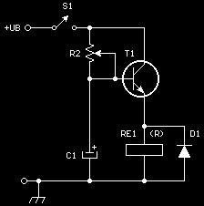
 The listed soft start connection is just one of many. It is more efficient to use less DC voltage from the source after the guidance. However, it is suitable for electronic output stages, in which we have only glow and anode voltage available. However, with a 6V heating voltage and a 5V relay, the capacitance of the capacitor would be very large, so the timing is solved with a transistor., as shown in the second scheme.
We need a DC voltage of the nominal voltage of the relay. When voltage is applied to the circuit, capacitor C1 begins to charge through trimmer R2. When the voltage across it exceeds the threshold voltage of the transistor, it opens and relay RE1 closes.
The advantage is, that the connection allows you to set the delay as needed. The trimmer has proved its worth in practice 100 kohm with capacitor 22 uF. The transistor is any NPN type, which has a collector current greater than the relay current and a collector voltage greater than the supply current. Diode D1 is protective.


