Anténu používa Mak SV1BSX na satelitnom uplinku (pôvodne najmä pre AO-40). Vyznačuje sa prijateľnými rozmermi (dĺžka boomu 1,5 metra), jednoduchou konštrukciou a impedanciou 50 ohm, čo umožňuje priame pripojenie napájača ku žiariču.
Mak SV1BSX: na úspešnú komunikáciu cez AO-40 je potrebné splniť na uplniku podmienku 150 až 200W ERP. Vzhľadom k tomu, že vúčšina komerčne vyrábaných zariadení má výstupný výkon v rozmedzí 15 až 25W, potrebujeme anténu so ziskom cez 10 dBd aby sme dosiahli požadované ERP.
Na základe poznatkov z rôznych home made konštrukcií ma najviac oslovil design ON1DHT. Desaťelementová anténa SV1BSX vychádza z tohto designu. V nasledujúci popis som doplnil o niekoľko poznatkov a analýz z programu YagiMax.
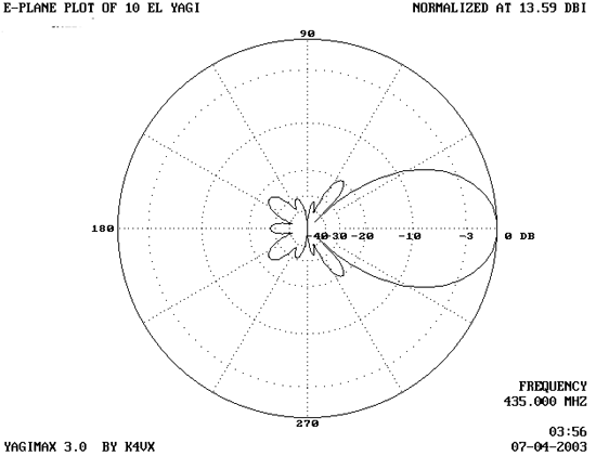
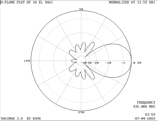
Anténa má zisk 13,59 dBi (11,5 dBd) a je pomerne malá, asi 1,5m dlhá.
Technické parametre 10 El UHF yagi
- Zisk 13.59 DBi (11.5 DBd)
- 26 DB F/B pomer
- 430-440 MHZ (SWR <1,5)
- SWR na 435 MHZ = 1:1
- Impedancia: 50 Ohmov
- Hor.vyžarovací uhol: 33°
- Vert.vyžarovací uhol: 38°

Anténa je ideálnym kompromisom medzi ziskom a veľkosťou… na zväčšenie zsiku o 3 až 4 dB by bolo potrebné minimálne zdvojnásobiť dĺžku boomu a zväčšiť počet prvkov. Daný zisk je vhodný aj na portbalovú prevádzku. Pri tejto dĺžke vychádza aj umiestnenie antény napríklad do auta práve akurát.
V článku sa dočítate
Konštrukcia
Anténa je konštruovaná na boome 15 x 15mm. Dipól je AlMg trubka s priemerom 8mm, všetky ostatné prvky s priemerom 5mm. Je veľmi dôležité dodržať všetky rozmery.

Na uchytenie antény na stožiar je potrebný držiak. V mojom prípade je umiestnený až za reflektorom. Nikdy, opakujem nikdy ho neumiestňujte medzi prvky antény. Z tohto dôvodu je aj boom trocha dlhší – 148,5 cm. Môžete použiť aj úchyt v ťažisku antény, ale musím byť z nevodivého materiálu alebo konštruovaný tak, aby stožiar a úchyt nezasahoval do priestoru antény.
Dipól
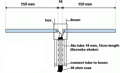
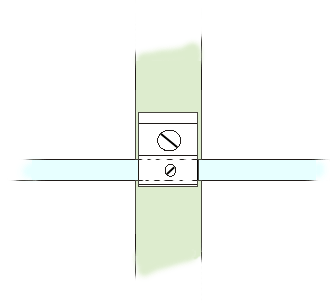
Dipól je izolovaný od boomu. Vhodná je plastiková krabička. Ja som použil krabičku z továrenskej TV antény. Všetky ostatné prvky sú vodivo spojené s boomom. Ako úchytky som si vyrobil alumíniové pásiky a každý prvok je navyše v prostriedku uchytený k boomu skrutkou. Viac napovie obrázok nižšie.
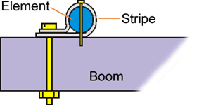
Druhá skrutka slúži na zafixovanie polohy prvku.
Bazooka
 Anténa využíva bazookový spôsob symetrizácie na spojenie symetrického dipólu a asymetrického koaxiálneho kábla. Trubka je pri reflektore vodivo spojená s boomom kovovou svorkou.
Trubka má priemer 10mm a jej dĺžka je 15cm. Koaxiálny káble prechádza cez trubku a pripája sa na žiarič. Priemer trubky je vhodný pre tenšie káble (RG-58, AirCel 7 a pod.). Ak použijete hrubší kábel, zväčší sa priemer trubky, ale jej dĺžka sa nemení.
Pozn.prekladateľa: tento spôsob symetrizácie sa používajú aj niektoré komerčné antény, napr.F9FT. Ponúkajú sa ešte dva spôsoby symetrizácie, a to prichytenie koaxiálneho kábla vo vzdialenosti lambda/4 od žiariča k boomu alebo koaxiálnym pahýlom.
AO-40 uplink
Na portablovom aj domácom QTH používam túto anténu na uplink s vertikálnou polarizáciou. Na portablovú prevádzku mám Kenwood TR-9500, ktorý dáva po úprave 15 až 17W (originálne 10W). Kábel od TCVR-a je relatívne krátky, iba 1,35m (3x lamba x k). S touto konfiguráciou som nadviazalo množstvo spojení cez AO-40. ERP je asi 150W (15W z TCVR-a krát 11,5 dB anténneho zisku mínus 1 až 1,5 dB strát v konektoroch a koaxiálnom kábli).
k – skracovací činiteľ koax.kábla
Na domácom QTH používam ten istý TCVR, ale koaxiálny kábel je dlhší (4 až 5 dB strát). Takto som však nemohol splniť podmienku ERP pre uplink. Vyriešil som to umiestnením malého UHF PA priamo pod anténu. Výkon na TX som stiahol na 5W, čo stačí na vybudenie PA na 20W. ERP je teda 20W z PA krát 11 dB zisku antény – vyše 200W ERP!
Anténa je vhodná nielen ako satelitná uplink anténa, ale vďaka dobrým vlastnostiam a veľkej šírke pásma sa hodí pre akúkoľvek prevádzku medzi 430 a 440 MHz.
Makis, SV1BSX
http://www.QSL.net/sv1bsx/
