Amplifier on 144 MHz s MRF9180 / MRF186
Cheap VHF amplifier
How to increase device performance on 144 MHz? One option is an LDMOS amplifier with MRF9180. These amplifiers are available as kits from various, mostly chinese, resellers on portals like Ebay, Amazon or Aliexpress. Their price is up to 40 €. However, such a kit requires still other components such as a power supply, cooler or RX / TX switching system and mechanical solution, resp. also the protection module. The total price will be higher. However, you can get a quality amplifier at 144 MHz with high gain.
The choice of MRF9180 was also given by that, that I have stabilized power supply 28V / 9A with toroidal transformer. Virtually the same type of amplifier can be fitted with other MOSFETs, e.g.. MRF186 or MRF9120.
VHF amplifier documentation MRF9180
The disadvantage of ordering a kit is the absence of relevant documentation. Fortunately, it is possible to obtain the necessary information on the web, for example GM4JTJ.
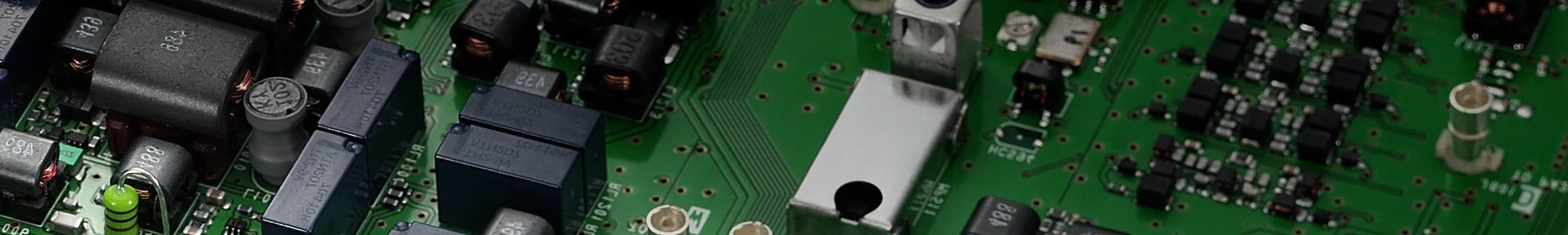
The kit came to me about three weeks after ordering. The printed circuit board is well processed and the components have been sorted. MRF9180 and ATC capacitors were used, what the landlord pointed out in advance. That's why I measured the MOSFET in advance, but fortunately it was functional.
In contrast to the drawing of the assembly of components and description GM4JTJ They are some components of other values and therefore I recommend to make a plan at the beginning how to install them. For example, the blocking capacitors in the supply line may have different values, but I do not recommend changing the values in the HF branch.

PCB mounting of VHF amplifier with MR9180
PCB mounting start by fitting the SMD components in the power supply branch.
After installing these parts, I continued ATC capacitors. Attention must be paid to the correct values. It is ideal to measure the capacity of capacitors.
Coolant outlet filter coils are wound on a drill. The most expensive is to make transformers. Input transformer has a thread ratio 3:1 (it gives a transformation ratio 9:1). It is necessary to wind with feeling, so that the insulation on the conductors does not dry out.
Output transformation is formed by circuits of 25- and a 50-ohm coaxial cable. The supplied kit contains a 50-ohm coaxial cable red, 25-ohm cables blue. Both cables are relatively hard and more difficult to strip. It requires good tools and a certain hand.

After mounting these components follows correctness check. We are not installing MRF9180 yet. We check the printed circuit board visually and then with an ohmmeter for unwanted short circuits. This is followed by the connection of the power supply and the voltage check on the drain and gate MRF9180 surfaces. The bias control circuit should allow the voltage to be set continuously from 0 po cca. 5V.
Now we can install MRF9180. After loading the input and output, it is possible to test the setting of quiescent current. I was a little worried about possible oscillations, whereas a MOSFET has a high gain, but the amplifier appeared completely stable. The quiescent current is set to 800mA. With increasing temperature, I registered its increase.


First testing of VHF amplifier with MRF9180
I did the first test with a HF signal using a HF generator and a HF probe. That confirmed profit approx. 17 dB. Because I was afraid of the possible destruction of MRF9180, so I mounted the input of the amplifier damping link.
Wake up from Kenwood-a TR-751E (5W) gives an output power of approx. 100W. Consumption at 28V is 7.2A, thus the efficiency of approx. 50%. Cooling is provided by a copper CPU cooler with a turbine. It is regulated by a bimetallic switch, which bridges the ballast resistor.
Switching and additional circuits of VHF amplifier with MRF9180
RX / TX switching circuits ensure relay switching QN59925 and auxiliary relays at the input of the amplifier and switching on the bias voltage. The circuit uses an exciter ULN2003 in standard connection.
Directly on the printed circuit board of the amplifier is also direct and reflected power detector, which allows you to create a PSV meter. It was a shame not to use this option.

Mechanical solution of VHF amplifier with MRF9180
The amplifier is built into a cabinet from an old measuring device. The front and back panels are made of kuprextite and a printed label on A4 adhesive foil. It is sprayed with several thin layers of clear lacquer to improve the durability.
Evaluation, advantages and disadvantages of VHF amplifier with MRF9180
The amplifier behaves very well in practice. I did not notice any activation of the second stage of the cooling turbine speed during SSB operation, t.j. 50° C on the sensor on the copper heatsink. I had a lot of material in stock, so I estimate the construction costs at 50 € in total. However, the construction is not suitable for beginners and can be enjoyed even by an experienced radio amateur.
But there is a certain risk quality MRF9180 from China. For many designers, the amplifier did not work due to a failure of this circuit or very soon LDMOS went to the silicon sky. One piece of MRF9180 stopped working for me too. Several sources recommend purchasing LDMOS from trusted resellers. In such a case, the reliability is said to be many times higher.


