Surge protection a little different
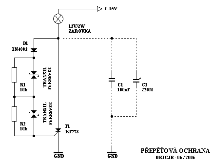
In a discussion on the FT817 forum – FT817ND was mentioned surge protection. Thyristor or transils were discussed. Since transils are relatively new parts for me, I was thinking about combining the advantages of a transil and a thyristor, that is, about a very fast reaction and a large current. In the end it turned out, that the optimal connection is according to the diagram.
As I read, transil is basically a Zener diode with a changed characteristic. The curve of the characteristic in the final direction is sharp, so the diode goes into the Zener voltage region very quickly.
Overvoltage protection wiring
I bought two pieces of transil marked P6KE6V8CA. They are bipolar transils. Unipolar, which fit perfectly, had GM sold out. After measurement, one transil had a voltage of 7.08V, the second 7.01V and about 0.75V is needed to open the thyristor. I.e, that the protection works at 14.88V. This is very satisfying. It's even better, that the voltage can be gently supplemented by ordinary silicon diodes connected in the forward direction. This will increase the protective voltage to the optimum 15,56 V. To remove a significant part of the tips, either induced or obtained from VF, however, blocking capacitors are required. However, it is true, that these blocking capacitors are already installed in decent power supplies. Usually directly on the output terminals.

I purposely did not use any capacitors in the control circuits, because they increase the response time. Parallel resistors to transistor circuits are used for correct distribution of voltage to individual transistors. Without these resistors, the voltage is distributed to the transils according to their internal resistances in the closed state. This is not guaranteed or stated in the technical sheets. This can cause a problem when opening. This is one example of many myths, that without the resistors the wiring will work maybe ninety percent. But the ten percent…
During operation, the bulb is of course omitted and the circuit is connected directly. I had the light bulb on for testing just because, so that I can read the voltage when the thyristor is turned on. One of you recorded an ISS crew, that this connection could work. But only time will tell. So far it runs in one version without problems.

Note: If the voltage is suitable, only one transil can be used. Then the resistors are removed and the entire circuit has only two components. During the tests, I wanted to verify the function when the transils are connected in series and the possibility of fine adjustment using a series diode.
73! Health Jarda OK1CJB
http://ok1cjb.nagano.cz


