
The Hentenna is one of the lesser-known but technically interesting antennas that originated in the amateur radio community. At first glance, it resembles a narrow vertical rectangular frame, but its radiation is predominantly horizontally polarized. It is this unconventional combination that gave the antenna its name, "Hen", which means "strange" or "strange" in Japanese.
In recent years, the Hentenna has been gaining attention again, especially among QRP operators, SOTA activators and experimenters on the 10m, 15m and 6m bands. The reason is its relatively simple mechanical construction, low radiation angle and higher gain than a conventional half-wave dipole.
In the article you will read
History of Hentenna
The antenna originated in Japan in the 1970s. It was developed by radio amateurs JE1DEU, JH1FCZ and JH1YST, who were experimenting with different loop antenna shapes. The English-speaking professional public became familiar with the Hentenna only after the publication of the article "The Hentenna – The Japanese Miracle Wire" in QST magazine in the early 1980s.
According to available sources, the antenna was originally designed for the 50 MHz band, but the principle is easily scalable practically from HF bands to VHFIn Japan, it gained popularity, especially among operators who required a simple antenna with higher gain than dipól, ale bez mechanickej náročnosti smerových sústav.
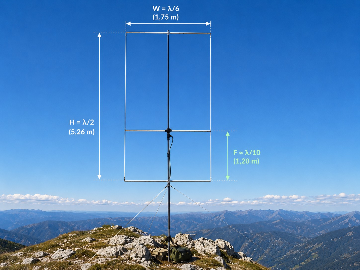
The hentenna is essentially a rectangular loop with a total conductor length of approximately 4/3λ and a feed cross conductor located approximately 0.1λ from the bottom.
TIP: The quad antenna shape can increase gain
Interestingly, the Hentenna's principle is based on a loop antenna. Earlier experiments with quad antennas have shown that stretching a square frame into a rectangular shape can bring some increase in directivity and gain. A similar effect is used by the Hentenna.

A classic square loop has a uniform current distribution around the circumference. A rectangular frame with a height of approximately λ/2 and a width of λ/6 produces a more favorable current distribution, which leads to a lower radiation angle and a slight increase in directional effect compared to a simple dipole.
The resulting radiation pattern has a characteristic shape of two main lobes perpendicular to the antenna plane. The Hentenna is therefore not an omnidirectional antenna. When properly oriented, it can provide a noticeable advantage in DX operation.
Hentenna parameters
Measurements and simulations published in the peer-reviewed paper “A Study of Hentenna” show that the basic model achieves a directional gain of approximately 3 dBd, with the radiation maxima located in two opposite directions. The simulated directivity values ranged from approximately 2.9 to 3.3 dBd, depending on the exact position of the feed element.

Practical measurements confirmed horizontal polarization and a low beam angle. Austrian radio amateur OE9HRV in his presentation It reports an elevation angle of approximately 13°, which is a favorable value for DX contacts.
However, one feature should be noted. A detailed analysis has shown that the classic Hentenna is a relatively narrow-band antenna. Therefore, it is necessary to pay attention to the exact location of the feed point and careful tuning of the dimensions. By moving the feed bar up/down, you change the impedance transformation ratio, which is a huge advantage, because you do not need to cut the antenna itself.
Basic electrical properties
| polarization | Horizontal |
| Radiation pattern | Bidirectional |
| Profit | Approximately 3 dBd |
| Beam angle | Low, suitable for DX operation |
| Impedance | Approximately 50–75 Ω after fine tuning |
| Bandwidth | Relatively narrow |
Hentenna dimensions
The basic geometry of an antenna is very simple. Most published designs use the same aspect ratios:
| Height H | λ/2 |
| Width W | λ/6 |
| Power supply position F | Approximately λ/10 from the bottom conductor |
For the 10 m (28 MHz) band, these ratios correspond approximately to the following dimensions:
| Height | 526 cm |
| Width | 175 cm |
| Power point | 120 cm from the bottom |

These values correspond to the practical designs of OE9HRV and DL3TU, who published successful implementations for the 28 MHz band.
Construction
Mechanical implementation is one of the main advantages of Hentenna. The antenna can be built from copper wire, aluminum tubes or a combination of both materials.
The most commonly used is a telescopic fiberglass mast. It has transverse struts at the top and bottom, between which a rectangular frame is stretched. A feeder wire connects the two vertical sides at a distance of approximately one-tenth of a wavelength from the bottom edge.
The correct placement of the feed point is an important element. Simulations have shown that its location has a significant impact on the input impedance and PSV. The most commonly reported distance in the literature is approximately λ/10 from the bottom conductor, with a slight shift up or down allowing fine-tuning of the match to 50 Ω coaxial cable.
Pri prenosných verziách pre SOTA sa osvedčili hliníkové rozperky s priemerom 6 až 12 mm a lankový vodič s prierezom približne 1 až 1,5 mm². Celá antenna pre pásmo 10 m môže mať hmotnosť okolo jedného kilogramu bez stožiara.
YouTube video
For a better idea of the practical implementation and operation of Hentenna, it is worth watching a demonstration by OE9HRV, who successfully uses the antenna in SOTA activities.
The video documents real-world operation in mountainous conditions and shows that the Hentenna can be an interesting alternative to a dipole or vertical in portable operation.
Practical experience
Several published experiments suggest that the Hentenna can outperform a simple dipole in certain situations. However, the results depend on the height above the terrain, the orientation of the antenna, and the current propagation conditions.
Of particular interest are modern simulations for the 10m band, which show a gain of approximately 8 to 9 dBi including ground effect when installed a few meters above the ground. These values cannot be directly compared to the gain of an antenna in free space, but they indicate the potential of the Hentenna for DX operation from suitable sites.
Conclusion
The Hentenna represents an interesting alternative between a simple dipole and a full-fledged directional antenna. Its main advantages are simple construction, relatively high gain considering the materials used, low radiation angle, and the possibility of implementation without a complex mechanical system.
On the other hand, it should be noted that this is a single-band antenna, which requires precise dimensions and careful tuning of the feed point. However, for QRP operators, experimenters and SOTA activators, it can be a very interesting project that offers more than its simple appearance would suggest.