
Starší anténny Rotátor nemusí byť problémom len preto, že jeho pôvodný ovládací box nepozná USB, computer control or automatic satellite tracking. Often the mechanical part of the rotator is still fully usable, while elektronika riadiacej jednotky už nezodpovedá spôsobu práce v dnešnom rádioamatérskom pracovisku. Práve tu je zaujímavý projekt K3NG Rotator Controller (K3NG ovládač rotátora). Ide o otvorený projekt založený na mikrokontroléri Arduino, which creates an interface between the computer and the rotator or its original control unit. Depending on the hardware used, it can also function as a completely standalone controller.
The advantage of the project is not only the computer control itself. K3NG allows customization of the way of position sensing, motor control, brakes, manual buttons, display, rotation speed, and the way of communication with the software. For an amateur radio operator who has an older Yaesu rotator, a home construction, or a rotator with a non-standard interface, it may be more interesting to modify the existing device than to build an entire system from scratch.
In the article you will read
K3NG is not just a USB converter
The basic idea of the project is quite simple. Arduino receives commands from the computer via a serial interface, evaluates the desired Azimuth or elevation, reads feedback from the position sensor, and controls the outputs of the rotator based on the results. The computer does not need to know the specific electronics of the used rotator. It communicates via a supported protocol, and K3NG provides translation between this protocol and specific hardware.
Projekt je možné použiť iba pre azimut alebo pre systém AZ/EL. This is important, for example, with a satellite antenna, EME sústave alebo smerovej anténe pre VHF. Pri jednoduchom rotátore pre tribander the azimuth part is sufficient, while with Yaesu G-5500 or similar systems both axes can be processed.
Computer communication via GS-232
One of the most important features of K3NG is the emulation of interfaces known to amateur radio software. The project supports Yaesu GS-232A and GS-232B, Easycom, and according to Radio Artisan documentation, also DCU-1. Serial communication uses the standard USB interface of Arduino. This allows K3NG to behave as a computer-controlled rotator without the original rotator needing to have its own modern USB interface.
The practical significance is great. The program does not need to be specifically programmed for a particular older rotator. If it supports GS-232 or the relevant interface, it can communicate with K3NG. GitHub the project indicates compatibility, for example, with Hamlib/rotctl, HRD, N1MM a PstRotator. RigExpert also indicates use with modern logging and contest programs.
Arduino as the control brain

Arduino in this configuration is not just a USB–GPIO converter. The firmware performs the logic of the entire rotator. It must know the current position, target position, direction of rotation, limits, and according to the configuration, also the brake or speed. It also processes local buttons and commands coming from the serial interface.
The open-source code is one of the reasons why K3NG is significant for the constructor. The project is not a closed black box. The configuration is adjusted according to the specific hardware, and individual functions can be activated or deactivated. This allows for the creation of a simple controller for a single azimuth rotator, but also a significantly more complex AZ/EL system.
Range 360 to 719 degrees

When modernizing an older rotator, it is important that K3NG does not assume only the classic range of 0 to 360 degrees. The project supports 360° and 450° azimuth rotators, and according to the documentation, also systems with a range of up to 719°. For the 450° rotator, the firmware can utilize overlap to select a more advantageous direction of rotation.
This is practical for directional antennas that may pass through the north. For example, if the target is in an area where there are two mechanical paths to the desired azimuth, it may not be necessary to make almost a full rotation. However, correctly setting the actual mechanical range is crucial. G4HSK found with his G-5500 that his specific rotator did not reach the declared 450°, but approximately 445°. Such a deviation must be taken into account during calibration.
K3NG rotator controller in real construction
A practical idea of the system is provided by a video dedicated to the assembly of the K3NG solution by VK4GHZ. It shows the work with the control board, microcontroller, and display, and is particularly interesting for the constructor who does not want to remain only with the software part of the project.
When building, it is good to first separate the three parts of the system: position feedback, K3NG logic, and power interface to the motor. The Arduino should not be directly loaded with the motor. There must be appropriate relays, transistors, power drivers, or other interfaces according to the type of rotator between the microcontroller and the motor.
Position sensing determines accuracy

K3NG supports multiple ways to obtain information about position. These include potentiometers or analog voltage, rotary and incremental encoders, pulse outputs, and selected digital sensors. Documentation mentions, for example, HMC5883L, ADXL345, LSM303, HH-12/AS5045, and other options.
When modernizing an older rotator, it is therefore appropriate to start with the sensor. If the original rotator has a potentiometer mechanically connected to the shaft, its use may be simpler than modifying the mechanics. Conversely, in a homemade construction, an encoder or magnetic sensor may be more advantageous.
However, it is necessary to distinguish between the electrical range of the sensor and the mechanical range of the rotator. Arduino must receive a signal range that corresponds to the input used and the selected configuration. Incorrectly set feedback voltage will subsequently manifest as incorrect azimuth or elevation.
Hardware: Arduino, relays, sensors, and display
A simple circuit may include Arduino, inputs for azimuth and possibly elevation, several buttons, power outputs, and LCD. OK1HRA in its assembly guide shows Arduino Mini, USB interface, LCD, buttons, LED indication, transistors, and two relays. Outputs are routed separately to AZIMUTH and MOTOR, and a separate output is also designated for the brake.
This concept is particularly interesting for older rotators. It is not necessary to copy one specific circuit. The power part must be adapted to the motor and the original control unit. In some rotators, K3NG controls the original box, while in others, a power relay or semiconductor stage can replace its control electronics.
Relay and motor control

K3NG provides separate control outputs for rotation direction and, depending on configuration, also for elevation. PWM outputs and frequency outputs are also supported, as well as separate brake control. However, this does not mean that any motor can be connected directly to Arduino. The firmware output must always pass through an electrically suitable power stage.
Provides a very good lesson G4HSK design. In the Yaesu G-650C, whose control unit did not use relays to switch the motor, a four-relay module was added. The rotator itself only needed two relays for CW a CCW. Rezerva ďalších relé umožnila použiť rovnakú dosku aj s inými rotátormi.
What can go wrong in the power section
In K3NG, it is very easy to focus on the firmware and underestimate the power supply. This can lead to errors that look like software problems. For example, G4HSK recorded an approximately seven-degree positioning error after adding the relay board. The cause was neither calibration nor new firmware. A current of approximately 25 mA drawn by the relay coil caused a voltage drop and thus a change in measurement. The relay board was therefore subsequently powered from another source and a 5 V regulator was used.
It is a very practical experience for every own construction: analog position measurement and power supply of power elements should not be addressed independently of each other. If the position displayed by K3NG changes after adding a relay, the power supply voltages, ground potentials, and voltage from the sensor should be measured before modifying the firmware.
Calibration of azimuth and elevation
After electrical connection, the system is not yet ready for precise automatic positioning. K3NG must know the relationship between the value from the sensor and the actual angle. The project therefore includes calibration of azimuth and elevation and also supports calibration tables. Settings are stored in EEPROM, so changing a configuration constant in the program may not automatically overwrite a value that has already been stored in the microcontroller's memory.
G4HSK encountered this detail when changing the parameter for 450° rotation. The new value did not overwrite into EEPROM as expected. When changing the rotator or re-calibrating, it is therefore necessary to know which parameters are only in the source code and which have already been stored in memory.
Automatic positioning and slowing down
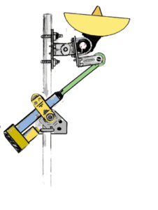
After proper calibration, K3NG becomes much more than just a remote CW/CCW button. The firmware can work with the target azimuth and automatic rotation. Optional slowing down when approaching the target, smooth start, manual limits, and use of overlap with rotators with a larger range are available.
For the radio amateur, this is mainly a difference in VHF, EME, and satellite operation. With manual adjustment, the position can be corrected several times, while with automatic tracking, the regulation must work repeatedly. G4HSK describes EME as a situation where precise adjustment of azimuth and elevation can have practical significance for a successful connection.
Manual control remains preserved
Computer control does not mean that local control must disappear from the controller. K3NG supports buttons for manual rotation and can display direction and current angle on the LCD. Classic character LCDs and selected I2C displays and Nextion TFT are supported.
For a simple station, however, the display may not be essential. G4HSK omitted the LCD in his later construction because when using PstRotator information about both the current and target position was directly available in the computer. The result was a simpler box and less mechanical work.
Safety, limits, and parking
The rotator is an electromechanical device, and an error in control can mean more than just incorrect data on the screen. Therefore, K3NG includes command timeout, manual rotation limits, parking, AutoPark, and brake control. There is also an indication of overlap for rotators with a larger range.
However, software limits cannot automatically be considered a substitute for mechanical limit switches. If a specific rotator requires a physical limit on movement, it must also be addressed at the hardware level. When modernizing old equipment, it is essential to know its mechanical stops, gears, motor power supply, and method of brake control.
Safe control in practice
When testing, it is advisable to start without an attached antenna or with the mechanics in a safe position and first verify the direction. K3NG can be configured so that the CW command causes movement in the opposite direction than the designer expects if the power stage or sensor is incorrectly wired. In a dual-axis system, both AZ and EL must be verified separately.
The practical aspect of the finished solution is also shown by RemoteQTH. Their azimuth interface based on K3NG uses Arduino Nano, LCD, buttons, encoder, and three relays for CW, CCW, and brake. It is designed for standalone operation as well as computer control and supports an analog potentiometer for feedback.
Firmware adapts to a specific rotor
K3NG should be perceived more as a kit than as firmware that is simply uploaded to the Arduino and starts working. The source code contains the configuration of functions, pins, and settings. The builder chooses which parts they need: AZ, EL, type of sensor, LCD, buttons, brake, PWM, parking, or other functions.
This is also one of the disadvantages. The more functions are turned on, the higher the demands on the microcontroller and the number of available inputs and outputs. G4HSK noted in a later version of the firmware that the Arduino UNO was already at the memory limit with a more extensive configuration, and the Arduino IDE warned about the program size during compilation. Therefore, they used an older, smaller version of the firmware. This is the experience of a specific builder, not a universal requirement of the project for Arduino Mega.
From simple interface to automatic station
The most interesting thing about K3NG is precisely the range of possible implementations. At one end is a simple Arduino controller connected to the original control box. OK1HRA, for example, describes an interface with Arduino Mini, USB, LCD, buttons, and relays that can function as a PC interface or, when supplemented with power supply and power elements, as a replacement for the original controller.

At the other end is a fully functional AZ/EL system with sensors, display, automatic tracking, and connection to a computer. The firmware supports tracking of the Sun and Moon, GPS, real-time clock, and according to the current documentation, satellite tracking as well. Compatibility with Hamlib/rotctl, N1MM and PstRotator then allows the rotor to be integrated into the existing amateur radio workspace.
In satellite operation, the combination of K3NG and tracking software is very practical. The computer calculates the required azimuth and elevation, and K3NG ensures the execution of the command. In EME, a similar architecture can simplify the precise pointing of the antenna at the Moon. In a contest station, it allows controlling the direction of the antenna directly from the program without separate manual adjustments.
Ready-made boards or custom construction?
K3NG does not have to mean making every resistor and relay from scratch. There are various boards and ready-made implementations based on the same firmware. RemoteQTH, for example, provides an open design of an azimuth interface with KiCad layouts, schematics, PCBs, and mechanical files. Their solution uses an Arduino Nano, three relays, an LCD, and an encoder in a compact design.
However, a custom board makes sense when it is necessary to adapt the interface to a specific old rotor. It may be necessary to change logic levels, add optical isolation, adjust relay power, customize the brake, or solve an atypical position sensor. It is precisely the open firmware that allows such modifications without the need to change the entire system.
What practical constructions show
The experiences of G4HSK clearly show why it is worthwhile to first understand the specific rotor in similar projects and only then assemble the electronics. With the G-5500, he used the existing interface, while with the G-650C, he had to add the relay part. During calibration, he encountered a difference between the declared and actual mechanical range and later also a problem with relay power. Such errors cannot be solved with a universal setting in the program.
That is why K3NG is most significant for the radio amateur willing to measure, test, and adapt the hardware. The project provides firmware and a communication layer, but the actual power and measurement interface must respect the specific rotor.
Where to start when modernizing an old rotator

The first step should not be uploading firmware to the Arduino, but documenting the existing rotor. It is necessary to determine the type of motor, power voltage, method of direction switching, presence of a brake, type of feedback sensor, mechanical range, and available connectors. Only then can the appropriate K3NG configuration be chosen.
If the old control box still reliably controls the motor, it may be simplest to leave the power section untouched and connect K3NG only to its external control interface. If the box is missing or damaged, K3NG can be the basis for a new controller, but then the power section, power supply, and protections need to be designed separately. OK1HRA and Radio Artisan directly mention the possibility of using K3NG as a replacement control unit or as the basis for a completely homemade system.
Innovation is also possible home made rotator for AZ/EL as vytvoril Mak SV1BSX už pred rokmi.
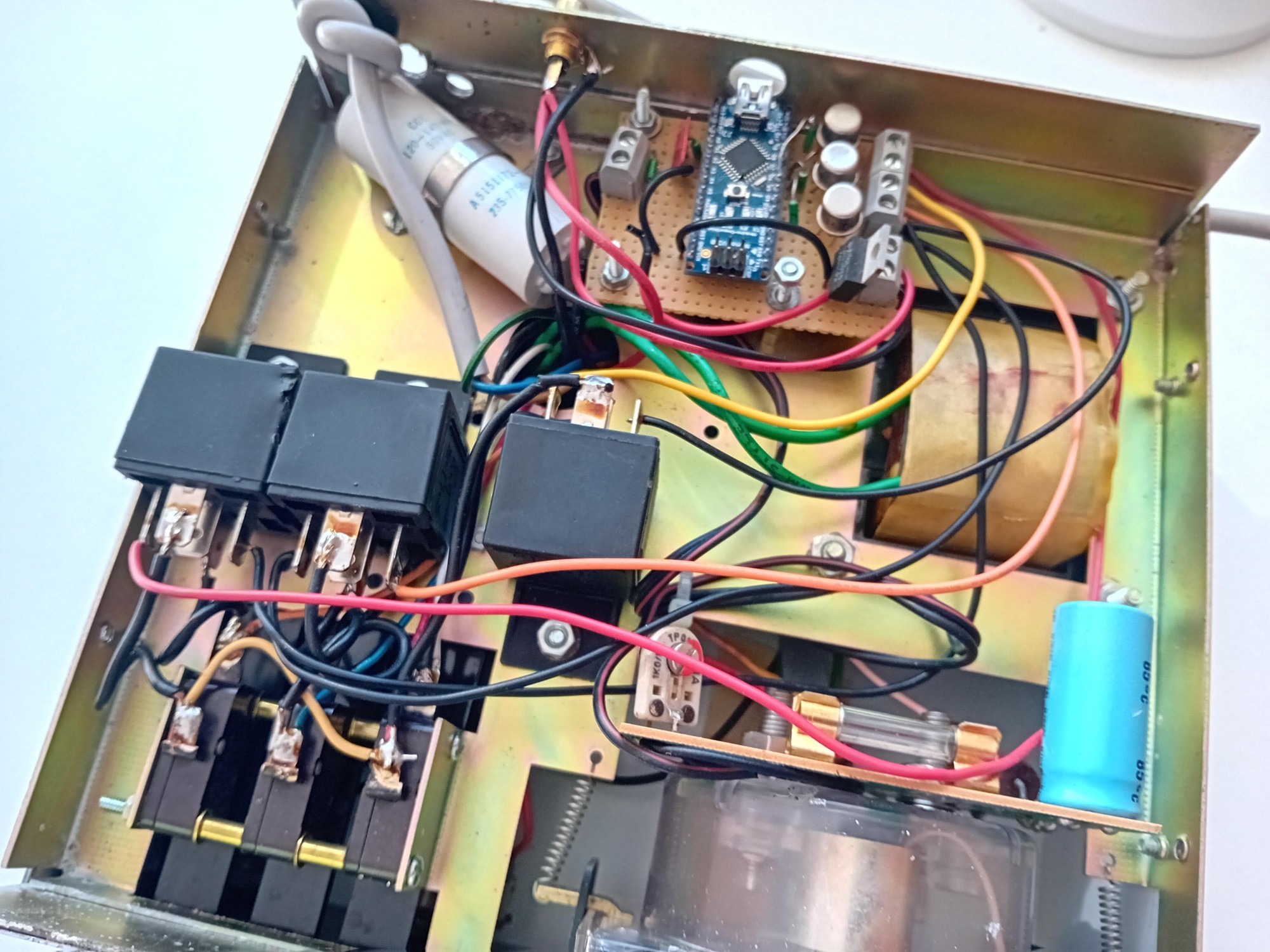
I have built the K3NG rotator controller several times. It is a very cheap and simple way to innovate an older rotator and especially to make operation more pleasant at the amateur radio workstation. I did not encounter any surprises during the construction, which is also a confirmation of feasibility. As can be seen from the photographs, it can also be implemented on a universal printed circuit board.
In the Hy-Gain / CDE CD-44 control box, there was enough space for more robust relays for the automotive industry.

If it is modified control box for rotators as AR-300XL, there is no problem connecting it to such a rotator. Due to computer control, I do not usually install a display or control elements – everything is controlled by PstRotator either manually or semi-automatically from the N1MM+ log, respectively. Gpredict pre satelitnú prevádzku.
K3NG rotator controllers as a path to a more modern old rotator
The value of the K3NG project does not lie in making a new model from an old rotator. The mechanics, motor, and sensors remain as they were. However, the control layer will change. The rotator can receive USB communication, automatic positioning, integration with Hamlib and tracking software, parking, a display, or new positioning sensing options.
For the amateur radio operator, it is essential that K3NG remains an open project. The source code is available on GitHub and its architecture is designed for customization. This allows the same foundation to be used in an old commercial rotator, custom mechanics, and experimental AZ/EL systems.
Therefore, the best approach is not to blindly copy one schematic. It is much more sensible to take from K3NG what a specific station needs and to design the power part according to the actual electrical and mechanical properties of the rotator. In this way, even a several-decade-old rotator can become a fully functional part of a computer-controlled amateur radio station.