V článku sú popisované metódy merania SWR a impedancie antény ako aj problémy s tým spojené. Hneď v úvode však treba poznamenať, že prípadný záujemca o stavbu sa tu už nezaobíde bez základných znalostí programovania či už PC alebo mikroprocesorov. Hardwarová jednoduchosť je vykúpená komplikovanejšími matematickými výpočtami.
V článku sa dočítate
1. Základný princíp
Na meranie komplexnej veličiny akou je impedancia antény sa používajú výlučne mostíkové metódy. Tieto pracujú s dostatočnou presnosťou a pri vhodnom prevedení spracujú veľký rozsah kmitočtov až do GHz. Čiastočnou nevýhodou je potreba napájania generátorom meracieho kmitočtu s pomerne prísnymi nárokmi na spektrálnu čistotu a značným výkonom. Samotná mostíková metóda umožňuje rôzne druhy meraní nielen na anténach ale aj na vedeniach a napájačoch. Mostík tohto typu je použitý aj v známom prístroji MFJ259. Zapojenie je až triviálne jednoduché:
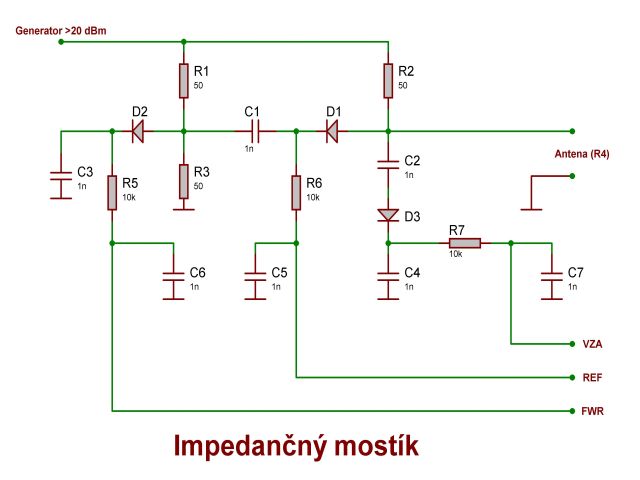
Po pripojení generátoru, nastavení požadovaného kmitočtu a pripojení komplexnej záťaže (antény) mostík dodáva tri napäťové informácie, ktoré postačujú na výpočet impedancie aj PSV (SWR). V ďalšom popise sa budeme držať tohto značenia:
FWR…..polovičné napätie generátoru meracieho kmitočtu
REF…..rozdielové napätie v diagonále mostíka charakterizujúce PSV
VZA…..napätie na meranej záťaži komplexného charakteru
2. Praktické prevedenie
Vzhľadom na nelinearitu diód v oblasti usmerňovania malých napätí použitých ako detektory je nutné aspoň čiastočne vykompenzovať túto nelinearitu a výstupné napätia zosilniť na dostatočnú úroveň pre potreby merania. Kompenzačný zosilňovač jedného kanálu je na nasledujúcom obrázku:

Každý z výstupov mostíka má takýto vlastný zosilňovač. V praktickom prevedení nastavíme rovnaké zosilnenie každej vetvy odporom R2. Dióda D1 by mala byť toho istého typu ako je použitá v mostíku. Najvhodnejšie sú Shotkyho diódy s vlastnosťami ZERO BIAS určené špeciálne na detekciu malých napätí, napr. 1PS79B62 (Philips) vyhovujúca až do GHz, ale do 500 MHz ich výber je viac ako bohatý… Veľmi vhodné sú trojité typy napr. HSMP-386L firmy Agilent, ale vyrába ich mnoho výrobcov. Operačné zosilňovače sú typu RAIL to RAIL s jedným napájaním, tých je tiež požehnane.
Odpory v mostíku R1, R2 a R3 by mali byť bezindukčné, napr.1206 ale veľmi vhodné sú aj TR191 bez drátových vývodov, ktoré sa dajú používať až do niekoľko GHz. Na absolútnej hodnote nezáleží, dôležité je aby mali rovnakú hodnotu, ktorá sa potom zahrnie do výpočtu ako Rx.
3. Generátor meracieho kmitočtu
Je možné použiť ľubovoľný generátor požadovaného kmitočtového rozsahu s dostatočným výkonom aspoň 20 dBm a malým skreslením. Vyhovujú bežné LC oscilátory, do 500 MHz je možné bez problémov urobiť zmiešavací generátor. Nasledujúci príklad ukazuje možné riešenie pre oblasť krátkych vĺn. Na internete si môžete vyhľadať podrobnú schému KV analyzátoru pod názvom RAINBOW z ktorého je nasledujúca schéma:
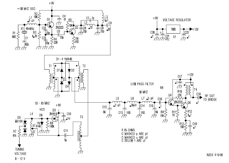
Použité súčiastky sú úplne bežné. Dokonca všetky širokopásmové, impedančné transformátory a dolné priepuste nemusíte ani navíjať a ladiť. Americká firma Coilcraft http://www.coilcraft.com/ to všetko má vo svojom výrobnom programe a naviac to zasiela aj do takejto banánovej republiky celkom zadarmo – stačí vyplniť formulár a trochu po anglicky pokecať. Aspoň mne to funguje dodnes už asi dva roky…
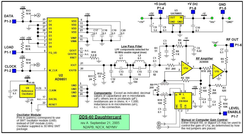
Elegantné riešenie generátoru pre oblasť KV až do 50 MHz je pomocou obvodu DDS, čo je priama kmitočtová syntéza. Rozšírené je zapojenie s IO firmy Analog Devices typ AD9851 ktorého prepracovaný príklad je na nasledujúcom obrázku. Obvod sa spravidla ovláda mikroprocesorom, čo je vhodné riešenie, lebo okrem iného odpadajú problémy s meraním kmitočtu – programovacie slovo zodpovedá kmitočtu, ktorý je možné jednoducho zobrazovať. Podobné riešenie bolo svojho času popisovane aj v RŽ 3/98.

Treba povedať, že firma vyrába aj výkonnejšie obvody DDS pracujúce na omnoho vyšších kmitočtoch. Tie sú pre amatérske použitie menej vhodné (veľa nôh, malé puzdrá) a sú veľmi drahé. Okrem AD niektoré takéto obvody vyrába aj firma HP ale pre amatérov bez väčšieho významu.
4. Vlastný výpočet
Výpočet sa prevádza v absolútnych jednotkách – Volty, Ohmy, Farady a Henry – tak sú zostavené nasledujúce vzorce. Predpokladáme, že merací prístroj nám ukazuje skutočné napätia všetkých troch veličín a generátor dodáva kmitočet Fx o výkone 20 dBm (100mW/2.2V/50 Ohm) spektrálne čistý ako „slovo Božie…“:
Pomer stojatého vlnenia – PSV , treba skontrolovať limitné hodnoty REF, pre ktoré nemá význam pokračovať vo výpočte, lebo PSV by vychádzalo príliš vysoké:
PSV = (1 + P) / (1 – P)
Určenie charakteru impedancie:
- Zvýš kmitočet generátoru Fx o malú hodnotu
- Znovu vypočítaj hodnotu charakteristickej impedancie Z1 = (Rx * VZA) / (FWD – VZA)
- Ak Z1 > Zo potom impedancia je induktívneho charakteru L
- Ak Z1 < Zo potom impedancia je kapacitného charakteru C
Ak by ste sa rozhodli postaviť si takýto analyzátor a použiť pre výpočet mikroprocesor s prevodníkmi napätia napr. PIC… alebo AWR… doporučujem 10-bitové typy. Referenčný rozsah AD prevodníka potom nastavte na 2.5V a pri programovaní si nezabudnite uvedomiť, že načítaná bitová hodnota meraného napätia v registri má od skutočného „hodne ďaleko…“ a treba ju previesť na reálnu hodnotu:
5. Eliminácia chýb merania
Ako vidieť z predchádzajúcich výpočtov značný podiel chyby pri výpočte impedancie je spôsobený nepresnosťami stanovenia PSV. To je pochopiteľné lebo pri nízkych hodnotách PSV je merané napätie REF v oblasti najnelineárnejšej časti charakteristiky diódy, ktorá sa nedá vykompenzovať a tak sa chyba prenáša do výpočtu reálnej aj imaginárnej časti impedancie. V hraničných podmienkach môže chyba presiahnuť aj 15-20% čo výsledky merania znehodnotí.
Našťastie existuje elegantné riešenie stanovenia PSV použitím špecializovaného obvody firmy MAXIM-DALLAS typu MAX2016. Obvod je tvorený dvoma logaritmickými detektormi pracujúcimi v rozsahu kmitočtom od LF až do 2,5 GHz a s dynamickým rozsahom až 80 dB. Podrobný popis a použitie obvodu nájde záujemca na Maxim-IC.com kde sa dá stiahnuť datasheet. Jeho veľkou nevýhodou pre amatérske použitie je puzdro QFN-28 o rozmeroch 5x5mm, ktoré sa dá zaletovať len technológiu povrchovej montáže. Uvediem preto len principiálne zapojenie pre meranie PSV a s tým súvisiace výpočty hlavne pre tých, ktorý nevedia anglicky.
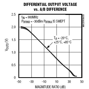
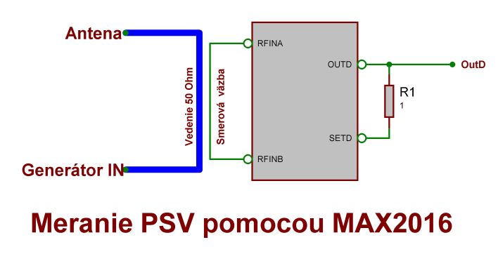
Smerová väzba (vytvorená napr. vedením plošného spoja) je pripojená na vstupy logaritmických detektorov. Výstup OutD je výstupom vnútorného diferenciálneho zosilňovača, ktorého vstupy merajú rozdielové napätie výstupov logaritmických detektorov. Vlastný výpočet je v princípe jednoduchý. Najskôr sa vypočítajú straty odrazom RL v dB (meranie PSV sa v profesionálnej praxi málo používa, prevláda vyjadrenie odrazových strát v dB):
VoutD……Rozdielové napätie prepočítané na absolútnu hodnotu vo [V]
Vcenter….Stredné výstupné napätie OutD, typicky 1V pre R1 = 0, ako to vidieť z priloženého grafu
Slope……Smerník prevodu mV/dB, typicky 25mV/dB pre R1 = 0
Zo strát odrazom vyjadrených v dB sa jednoducho vypočíta hodnota PSV:
PSV = (1 + P) / (1 – P)
Logaritmické detektory použiteľné pre tento účel vyrába aj Analolog Devices napr. AD8362, alebo typ AD8364 veľmi podobný MAX2016 ale v ešte „nepodarenejšom“ 32 vývodovom puzdre o rozmeroch 5x5mm. Všetky tieto obvody sa dajú použiť na meranie zisku, výkonu na reálnej záťaži, ako citlivý merač RSSI pre smerovanie a nastavovanie antén a pod.
Dnes už každá serióznejšia firma poskytuje svojim zákazníkom rozsiahlu technickú pomoc zahrňujúcu aj vývoj aplikácií ponúkaných integrovaných obvodov a tie najlepšie aj zásielkovú službu FREE SAMPLES (Vzorky zadarmo). Bohužiaľ AD medzi ne nepatrí zrovna tak ako tie, ktoré majú v postkomunistických krajinách zastúpenie.
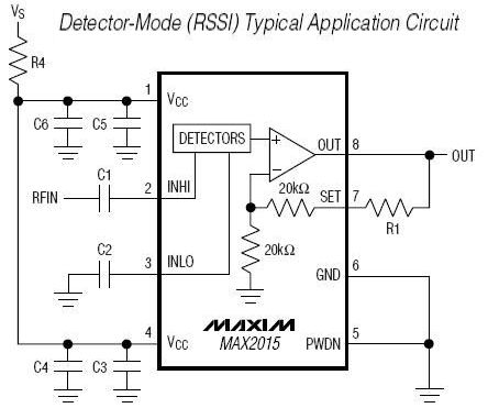
Firma DALAS-MAXIM vyrába aj iné typy logaritmických detektorov jeden z nich MAX2015 je na obrázku vľavo v zapojení ako citlivý detektor RSSI. Ide o jednokanálový typ z vysokou citlivosťou -65dBm až +5dBm (citlivosť 0.125mV/50 Ohm) v kmitočtovom rozsahu 0,1 až 2,5 GHz. Je umiestnený v SMD puzdre 8uMAX, ktoré je pre amatérske použitie viac vhodné.
V katalógu firmy nájdeme množstvo ďalších, pre rádioamatéra zaujímavých obvodov ako je napr. MAX2620 čo je LC oscilátor do 1050 MHz, oddeľovacie, širokopásmové zosilňovače a pod. Škoda len, že väčšina z tých najzaujímavejších je v miniatúrnych SMD puzdrách čo komplikuje amatérske použitie. Žiaľbohu taký je svetový trend a možno o 10-15 rokov už diskrétnu súčiastku budeme poznať len poniektorí skôr narodení…
Najlepšie na tom však je, že bežne posiela z každého vybraného typu po dva kusy ZADARMO, takže sa naozaj oplatí navštíviť ich stránky aj keď v posledných mesiacoch zmenili štruktúru a odvtedy sa mi už nepodarilo dostať sa na FREE SAMPLE ORDER…ale možno to spôsobuje len nová, dokonale neodladená zásielková služba.
6. Merať alebo modelovať antény ?
…to je otázka. Ak uvažujeme KV pásma, meranie ani veľký význam nemá. Moderné modelovacie programy ako sú napr. MMANA, NEC-2, EZNEC, NEC WIN+ a iné nám poslúžia rovnako dobre ako anténny analyzátor. Navyše bez námahy a nákladov so zhotovením, pričom chyba s ktorou môžeme rátať je prakticky zanedbateľná a úpravy na anténe „robíme“ pohodlne doma pri stole. Nemusíme „zaskakovať“ opicu lezením po strechách.
Aj situácia s modelovaním v pásmach 2m a 70cm je podobná ak nie lepšia. Presnosť hardwarového merania mierne klesá so zvyšujúcim sa kmitočtom, zatiaľ čo matematické modelovanie (bez ohľadu na použitý algoritmus MININEC, NEC2 alebo NEC4 vždy ide o momentovú metódu a jednotlivé typy sa v podstate odlišujú len komfortnosťou obsluhy) dáva asi do 500 MHz udivujúco presné výsledky.
Ak máme v úmysle modelovať antény iné ako yagi, vertikály alebo drátové – napr.paraboly alebo Helical – výhodnejšie je použiť program pracujúci s algoritmom NEC, ktorý modeluje planárne alebo geometrické plochy ako celistvé štruktúry kým starší algoritmus MININEC (používa ho MMANA) počíta tieto štruktúry ako jednotlivé primitívy čo značne predlžuje čas výpočtu. Mimochodom, záujemcom o modelovanie antén dobre poslúži The unofficial Numerical Electromagnetic Code (NEC) Archives.
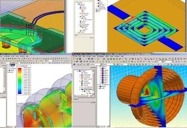
Iná je situácia na vysokých kmitočtoch. Ceny meracích prístrojov dosahujú astronomických výšok, ale ani modelovacie programy nie sú zrovna lacné…Zo známejších spomeniem GENESYS, HFSS92, ZELAND, MAXWELL_SV9 a mnohé iné, ktorých možnosti presahujú potrebu aj toho najnáročnejšieho rádioamatéra. Dokážu modelovať aj také štruktúry, ktoré sa prakticky nijakým spôsobom nedajú merať a mnohé technické riešenia by bez týchto programov nebolo možné realizovať!
A tak si milý priateľ musíš sám nájsť odpoveď na otázku. Merať alebo modelovať…?
(C)2006 Ivan Urda, OM7UR
