
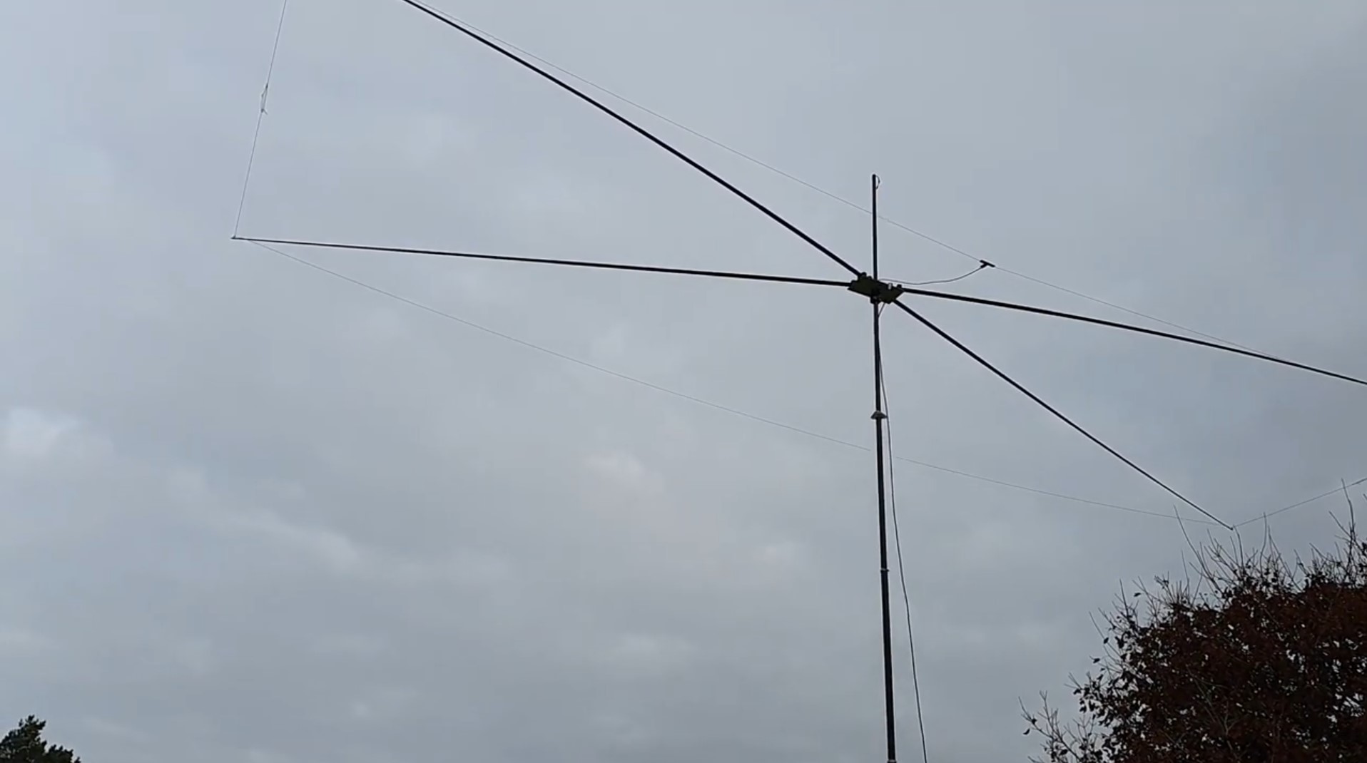
The Moxon antenna (Moxon rectangle) is a simple and mechanically robust two-element directional antenna for one frequency. It is a two-element yagi-Uda with a reflector and no directors, where the ends of both elements are bent towards each other - this creates the rectangular shape that gave the antenna its name. It is this construction that makes it a popular choice for field days, emergency communications and a regular home station.
You will read in the article
History of the Moxon G6XN antenna
Behind the design is Leslie "Les" Moxon, G6XN, a British radio amateur licensed as early as 1928. During World War II he was involved in top secret radar development, after the war he worked as a government radio engineering specialist until his retirement in 1969. He is best known as an author of books on antennas - his work "HF Antennas for All Locations" from 1982 (second edition 1993, RSGB) has become a classic of the field. According to Dean Straw, N6BV, an ARRL antenna technician, Moxon's knowledge of the effect of terrain on propagation was one of the factors that led him to become interested in this area of HF operation years ago. Moxon died on March 3, 2004, aged 95, in Surrey and was posthumously inducted into the CQ Amateur Radio Hall of Fame in 2005.
The very principle of the antenna was not completely created from scratch. It is based on the VK2ABQ square concept discovered by Fred Caton, VK2ABQ - if a square quad loop is laid horizontally and cut on two sides in the middle, it creates two isolated half-wave conductors with some directivity. Moxon made two major improvements: he found that the rectangular shape improved gain, and that the gap between the ends of the wires was critical for the antenna to function properly—it had to be greater than that provided by insulators used up to that time. In its original version, Moxon tuned both drivers remotely from the shack, resulting in a fixed but reversible beam. Later systematic modeling and documentation of the antenna was carried out by LB Cebik, W4RNL, who also developed his own method of calculating the native dimensions of the elements without the need for electrical fine-tuning.
Moxon's knowledge of the effect of terrain on propagation was one of the factors that led ARRL antennaist Dean Straw, N6BV, to take an interest in this area of HF operation—Moxon was, in his words, a true "radio pioneer."
Technical parameters of the Moxon antenna
A common two-element Yagi with a reflector has a boom length of about 0.2 λ and an impedance of 50 Ω. Moxon achieves the same impedance of 50 Ω with a boom length of only 0.18 λ, i.e. at approximately 70% of the length of the equivalent dipole. The ends of the elements, bent back (radiator) or forward (reflector), act as a capacitive load - which is more advantageous in terms of bandwidth and losses than inductive loading with coils.

Thanks to the reduced dimensions, the gain compared to a full-sized two-element beam is lower by approximately 0.2 to 0.7 dB, depending on the specific implementation. The compensation is an extremely high front-to-back ratio (F/B) - with a well-tuned design, it reaches values of 30 dB and more at the design frequency, which exceeds any other common two-element beam, including the ZL Special or HB9CV, which tend to keep the rear side lobes suppressed just below 20 dB. This property is created by a combination of parasitic coupling from parallel parts of the elements and coupling at the ends of the conductors (end coupling), while Moxon achieves this effect without using a phasing line.
| Parameter | Value |
|---|---|
| Antenna type | 2-element Yagi-Uda (radiator + reflector, without director) |
| Boom length | 0.18 λ (compared to 0.2 λ for a classic 2-element Yagi) |
| Impedance | 50 Ω (direct coaxial feed) |
| Profit | about 0.2–0.7 dB lower than a full-size 2-element beam |
| Front-rear ratio (F/B) | typically ≥ 30 dB at design frequency (according to DK7ZB) |
| Directionality | approx. 2.0 dB, with a wide frontal lobe of almost cardioid shape |
According to Cebik's modeling of the 20m aluminum Moxon, the gain varies only about 0.6dB across the band, while the F/B ratio at the band edges remains around 20dB. Impedance at the feed point stays close to 50 Ω across the band, so coax (with choke/balun) is a natural power choice without the need for matching members.
Video: Construction of the Moxon antenna
An overview of the advantages of the Moxon antenna
The main asset of Moxon is a combination of features that you cannot otherwise find in one construction: a high front-to-back ratio while maintaining a gain close to a full-size beam, all on a significantly shorter boom. For operators who prefer the principle of "good ears" over gross profit, this is an ideal combination - the Moxon significantly suppresses interference and QRM coming from behind.
Mechanical simplicity is another advantage. The construction does not contain any coils or phasing lines, the direct 50-ohm feed eliminates the need for complex adaptation. The portable wire versions of Moxon are popular for field days and emergency communications due to their light weight and durable construction. On VHF and UHF bands, the Moxon tends to be built from aluminum tubing approximately 3/8 to 3/4 inch in diameter, which provides a wider band without unnecessary wind load.

When designing for KV bands (for example 17m) users confirm that with accurate dimensioning they achieve an almost perfect 1:1 match at the design frequency, even without a balun, although a balun at the feedpoint is common practice. The bandwidth is sufficient for full coverage of, for example, the entire 17-meter band.
Antenna sketch and dimensions
The key dimensions of the Moxon are always indicated in the same way: A is the overall length of the radiator, B is the length of the "tail" (bent end) of the radiator, C is the gap between the ends of the radiator and the reflector, D is the length of the tail of the reflector, and E is the overall width of the antenna (the distance between the radiator and the reflector in the center).
According to Cebik's original modeling, length A primarily controls overall impedance, radiator tail B has the most immediate effect on feedpoint reactance, reflector tail D mainly affects feedpoint resistance, and gap C has the greatest effect on the location of the deepest null within the selected band.
DK7ZB publishes for the 144 MHz (2 m) band the following dimensions for aluminum elements of different diameters, with a boom made of 25 mm PVC pipe:
| Dimension | 2.4 mm | 3.2 mm | 4 mm | 5 mm |
|---|---|---|---|---|
| A – length of the emitter | 744 mm | 744 mm | 744 mm | 742 mm |
| B – the tail of the emitter | 104.5 mm | 102 mm | 99.5 mm | 98 mm |
| C – space | 29.5 mm | 32.5 mm | 34.5 mm | 37 mm |
| D – reflector tail | 141.5 mm | 141 mm | 141.5 mm | 141 mm |
| E – width (spacing) | 275.5 mm | 275.5 mm | 275.5 mm | 276 mm |
With this construction, the 2-meter Moxon achieves a DK7ZB gain of 4.09 dBd at 144 MHz, 3.89 dBd at 145 MHz, and 3.69 dBd at 146 MHz, with a front-to-back ratio of 20 dB, 33 dB, and 27 dB at these band points. The elements are made of aluminum welding rods, the coaxial cable is connected on the opposite side of the terminal and wound into a choke for symmetrical power supply. Konce prvkov sú spojené malými izolačnými trubičkami pre lepšiu mechanickú stabilitu.
For wired versions on KV bands (without insulation, 1 mm diameter wire), DK7ZB publishes, for example, the following dimensions: band 20 m – S (radiator) 1011 cm, R (reflector) 1057 cm, spreader F 411 cm; pásmo 17 m – S 788 cm, R 826 cm, spreader F 321 cm; pásmo 15 m – S 674 cm, R 706 cm, spreader F 275 cm. Kompletné tabuľky pre všetky pásma od 6 do 30 m sú publikované priamo na stránke QSL.net/dk7zb.
Practical tips from construction
It is advisable to choose the design frequency approximately in the first third of the band from its lower edge, since the SWR increases significantly below the design frequency than above it. Pri drôtových verziách nikdy neohýbajte konce vodičov do kruhu – fungujú potom ako koncový kondenzátor a spôsobujú posun frekvencie. Namiesto toho použite rovný Izolátor s presne definovanou dĺžkou.
In practical construction, for example, with fishing rods in X configuration, the critical point is the exact location of the point where the element bends 90 degrees - it is at this point that the conductor connects to the fishing rod. The experience of the builders confirms that if the dimensions are followed exactly, the antenna achieves an almost perfect 1:1 adaptation at the design frequency and can also withstand high power (kilowatt operation without problems).
Pre výpočet presných rozmerov podľa zvoleného priemeru vodiča a materiálu je najpraktickejšie použiť voľne dostupný program MoxGen by D. Maguire, AC6LA, which is based on Cebik's empirical formulas and also generates an output file for EZNEC for further modifications (for example tapering of elements). It is important to remember that the Moxon is a single-band antenna - attempts at multi-band versions with a common feed do not give satisfactory results; pre viacpásmovú prevádzku je potrebné buď samostatné napájacie vedenie pre každé pásmo, alebo úplne iný typ antény.
Video: Moxon antenna in test operation
My observations on the moxon antenna

The mechanical resistance of the moxon antenna is rarely mentioned. I noticed that it behaves differently in the wind than a classic yagi, where each element oscillates independently. By connecting the elements, it seems to me that the elements dampen each other's vibrations and are much calmer.
The rectangular shape is also practical for VKV portable - there are no ends of elements that get caught on something. I can throw the Moxon antenna in the trunk of the car without the elements getting tangled in any cables.
Vynikajúci F/B pomer môžem potvrdiť. The gain also corresponds to the declared 4dBd. A multi-element yagi, for example Optibeam OB10-3W má zisk 5,3 až 6,5 dBd (podľa pásma). In the battle of decibels, the moxon antenna loses. Also 2 dB already known. Ale spomínaný Optibeam má 10 prvkov, je dlhší, širší, ťažší aj drahší.
The Moxon antenna is quite sensitive to the environment. Nehodí sa napríklad na spoločný stožiar s množstvom iných antén, a to ani o 90° pootočených. This is due to the fact that the moxon antenna also uses parts of the elements that are bent by the aforementioned 90° for its operation, and thus interaction occurs.
Summary
More than thirty years after its publication, the Moxon antenna remains one of the most popular compact directional antennas among radio amateurs - partly thanks to its creator Les Moxon, G6XN, who perfected the original VK2ABQ square concept, partly thanks to the subsequent systematic modeling of L. B. Cebik, W4RNL. The combination of a high F/B ratio, a gain close to a full-size two-element beam, a direct 50-ohm feed and a significantly shorter boom make it a practical choice for both confined sites on the KV bands, as well as for field and portable VHF/UHF antennas. The exact dimensions must always be adapted to the chosen diameter of the conductor - if the published tables (for example from DK7ZB for the 2 m band) are followed, the design achieves repeatably excellent results without the need for complex tuning.