Ďalším článkom od Oleho OZ2OE je nízkošumový predzosilňovač na 144 MHz s BF981, ktorý dosahuje zisk 23 dB pri šumovom čísle okolo 1 dB.
V článku sa dočítate
Úvod
Možno si niekto položí otázku: prečo preduosilňovač s dvjbázovým MOSFET? Je možné samozrejme vybrať si z viacerých zapojení s GaAs FET, ale pre 2m tropo prevádzku nie je badateľný rozdiel, pričom MOSFET je oveľa odolnejší – a lacnejší!
Mechanická konštrukcia
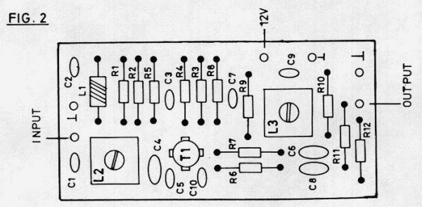
Predzosilňovač je skonštruovaný na obojstrannom plošnom spoji s rozmermi 25 x 50 mm. Vrchná strana slúži ako zem. Osadený plošný spoj je v malej kovovej škatuľke zakončený BNC konektormi.

Elektrické zapojenie predzosilňovača OZ2OE
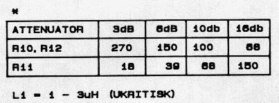
Zo schémy vidno, že vstupný obvod tvorí sériový ladený obvod, výstupný „normálny“ paralelný s kapacitnou väzbou. Pretože predzosilňovač má až príliš veľký zisk, je na výstupe útlmový článok. Predpätie pre tranzistor je realizované napäťovými deličmi v G1 aj G2. Takto je možné presne nastaviť jednosmerné parametre predzosilňovača.

L2, L3: 5,25 závitu Cu drôtom s priemerom 0,25 mm na teliesku Neosid K3312, F100 a pod.
Detaily zapojenia
Vstupná časť je riešená pomerne netradične so sériovou indukčnosťou L2, ktorou sa dosahuje prevod impedancie z 50 ohm na asi 1600 ohm, čo je optimálna impedancia pre šumové prispôsobenie. L2 rezonuje s C4 a G1 kapacitou tranzistora.
Tento spôsob minimalizuje záťažené Q obvodu – dôležité kvôli nízkym stratám – a správnemu impedančnému (šumovému) prispôsobeniu.
Výstupný paralelný obvod tvoria L3, C6 a C8. Kapcitný delič C6 – C8 určuje impedanciu na približne 2 kohm-y. To má tiež vplyv na zisk.

Naladenie predzosilňovača
Oživovanie začína najprv kontrolou odoberaného prúdu, ktorý by mal byť asi 20 mA. Potom stačí nastaviť už len L2 a L3 na miximum signálu.
Najvýhodnejší je slabý nemodulovaný signál priamo z pásma, ktorý privedieme do prijímača v FM móde. Nastavte L2 na najväčšie potlačenie šumu.
Pri FM signále na úrovni šumu FM detektor prijímača zosilní akékoľvek zlepšenie pomeru signál/šum, čiže na optimálne naladenie postačia vlastné uši! Akúkoľvek zmenu v zisku predzosilňovača eliminuje limiter FM prijímača.
Atenuátor
Ten si môžete zvoliť podľa vašich požiadaviek – ktoré nemajú byť „viac ako je nutné“. Nasledujúca tabuľka ponúka niekoľko možností:

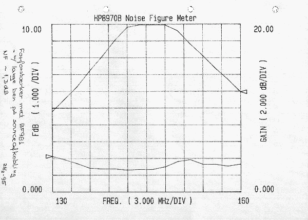
Vlastnosti predzosilňovača OZ2OE
Postavil som a odmeral množstvo týchto predzosilňovačov a väčšina mala identické vlastnosti. Typické vlastnosti s –3 dB atenuátorom sú v grafe:

Plošný spoj a súčiastky
Keď sa mi podarí previesť obrazec plošných spojov do vhodného formátu, umiestnim ho sem. Dovtedy najlepšie čo môžem ponúknuť je naskenovanie originálnej predlohy. Ak máte záujem, kontaktujte ma.
Tiež môžem pomôcť s osadzovaním plošného spoja a špeciálnymi kostričkami od Neosid-u.
Ole, OZ2OE
