PSU Designer II je program na návrh a analýzu nestabilizovaných zdrojov skladajúcich sa z transformátora, usmerňovača, filtra a záťaže. Napísal a zostavil ho Duncan Munro z firmy Duncan Amplification. Je šírený ako plne funkčná verzia. Vyžaduje W95+ a odpovedajúci počítač s myšou, či iným polohovacím zariadením.
V článku sa dočítate
Optimalizácia a výpočet zdroja s PSU Designer II
Ak si niekto myslí, že urobiť dobrý zdroj je hračka, potom ešte asi žiadny nerobil. Straty, úbytky napätí, zvlnenie, prehrievanie, pokles výstupného napätia… Práve pomoc pri optimalizácii zdroja poskytne PSU Designer II.
Inštalácia PSU Designer II

Práca v PSU Designer II
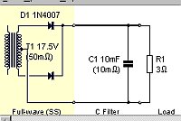
Okno programu je možné rozdeliť na tri časti: schému zapojenia, výsledky výpočtov a graf. Ak prejdeme kurzorom ponad súčiastky v schéme, ihneď sa pozadie pod nimi zmení z bielej na žltú. Kliknutím na pravé tlačidlo myši sa objaví nápis „Edit“ alebo „Change“ (záleží či kliknete na súčiastku alebo pomimo).
Ak vyberieme „Edit“, máme možnosť meniť hodnoty danej súčiastky. Napríklad pri transformátore je to výstupné napätie a odpor vinutia, pri dióde zvoliť jej typ, pri filtre hodnoty súčiastok z ktorých sa skladá a pri záťaži jej veľkosť.

Pred kliknutím na tlačidlo „Simulate“ máme možnosť nastaviť dĺžku simulácie a jej oneskorený štart po zapnutí. Pri oneskorenom štarte už nevidíme prechodové javy, ktoré vznikajú pri nabíjaní kondenzátorov a pod.
Výsledky výpočtov zdroja
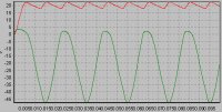
Výsledky výpočtov pozostávajú zo všetkých prúdov a napätí v obvode. Zobrazuje sa minimálna, maximálna hodnota a ich diferencia, priemerná a efektívna hodnota. Prúdy aj napätia je možné zobraziť v grafe a to tak, že zaškrtneme políčko vedľa prúdov a napätí, ktorých priebeh nás zaujíma.
 |
 |
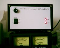
Mne tento program veľmi pomohol pri návrhu nového zdroja 13,8V/6A (TCVR a notebook) a 28V/9A (100W V-MOS PA). Ale o tom niekedy nabudúce.
Download PSU Designer II
PSU Designer II nájdete na https://www.CQ.sk/download/psud2_setup.exe.
