
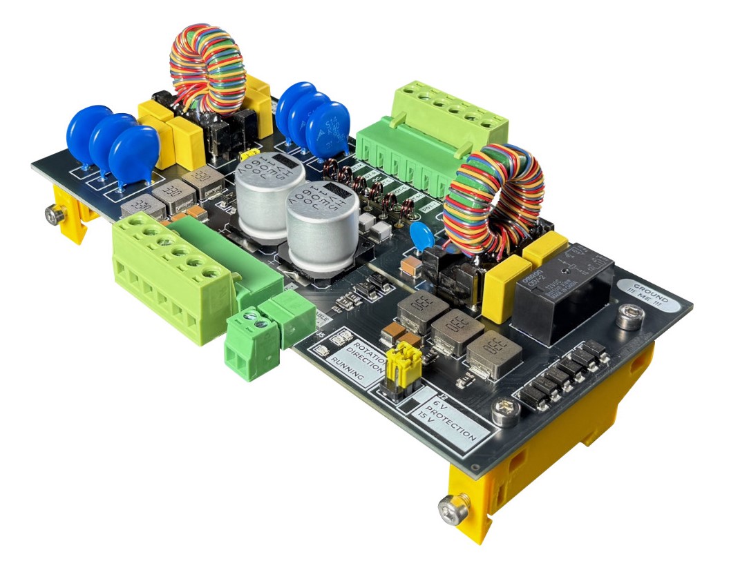
Anténny Rotátor is usually several meters away from the control unit, but often tens of meters. Therefore, a cable runs between the mast and the amateur radio workspace, which can carry high voltage or impulse overvoltage induced by a nearby lightning strike during a storm. Not only the rotator motor itself is at risk. Overvoltage can also enter the azimuth sensing circuit and subsequently into the control unit's electronics. HVROTY is a continuous protective module designed specifically for this part of the line – it protects the motor wires as well as the azimuth sensor line.
In the article you will read
Protection of the line between the mast and the shack
HVROTY connects to the cable between the rotator located on the mast and its control unit in the shack. The module does not operate as a standalone control system for the rotator. Individual wires pass through protective and filtering circuits and on the other side continue to the corresponding terminals. The line from the mast side connects to the terminals leading to the rotator, while the inner side connects to the control unit.

The protection has two separate circuits. The first is for the motor wires M/R/L, the second for the three-wire azimuth sensor line POT+, wiper, and GND. Both circuits have their own suppression of common mode interference currents and differential filtering. The maximum operating voltage of the module is 60 V AC/DC and the maximum current is 4 A.
Why a long cable to the rotator is a problem

A long conductor between the mast and the workspace represents an effective path during storm activity, where a significant potential difference may appear. It does not have to be a direct lightning strike to the antenna. Dangerous voltage can be induced into the conductors by the electromagnetic field of a nearby discharge. The protective circuit must therefore divert the impulse energy to a common ground point while simultaneously limiting the voltage that continues towards sensitive electronics.
HVROTY uses a combination of surge protectors and filters on both protected circuits. However, it is important to understand its purpose correctly: the manufacturer explicitly warns that the board is not designed to protect the device from a direct lightning strike. A comprehensive grounding and bonding system is required in such an event.
Protection of three conductors M/R/L
The motor section of HVROTY is designed for standard three-wire connections of rotators. Each of the conductors M/R/L is first protected against a common ground point using a 75 V gas discharge tube GDT. Following that is a 60 V varistor with a capacitor stage, three-phase common-mode choke, another varistor and capacitive stage, and a differential LC filter.
Such a configuration combines surge protection with suppression of high-frequency interference. GDT is designed to divert impulse surges, while varistors and filters further limit interference and residual impulses on the line. The motor section also has LED indicators ROT and DIR, which signal the activity of the line.
AC and DC rotators
HVROTY accounts for two common drive concepts. In the AC capacitor rotator, the winding leads and the phase capacitor circuit run through the module. A jumper J1 is available for these systems, which can connect a capacitor with a capacity of 100 µF. If the rotator uses its own capacitor or is a DC drive, J1 is not used according to the specific wiring.
In a two-wire DC motor, the motor is connected to two of the three motor terminals, and the direction change remains the task of the relay in the control unit. The manual states that the built-in capacitor can also be used in this case as an additional filter and to ensure smoother motor run-out.
Sensor azimuth protection

The second part of HVROTY protects the sensor azimuth wiring. In a classic potentiometric sensor, there are three wires - powering the potentiometer, the wiper, and ground. Here, a 75 V GDT is also used, followed by a 26 V varistor stage, a dedicated three-phase common-mode choke, and a differential LC filter.
After the filter, there are resettable fuses rated at 100 mA and a bidirectional protection stage. The potentiometer protection voltage can be set via a jumper to 6 V or 15 V depending on the power supply voltage used by the control unit. In an open configuration, the technical specifications indicate a value of 26 V. The state of the wiring is indicated by an LED RUNNING.
HVROTY also works with a pulse sensor
The sensor protection circuit is not limited to an analog potentiometer. The manufacturer provides laboratory verification with a rectangular signal at a frequency of 500 Hz, which passed through the input and output without issues. Therefore, the module can also be used with a pulse azimuth sensor. The technical specifications also state the passband for rectangular signals above 500 Hz.
Common-mode and differential filters
The three-phase common-mode choke is significant in HVROTY primarily for suppressing RFI. All three wires of the respective circuit pass through a common choke, allowing the device to suppress common-mode high-frequency interference without disrupting the function of the wires themselves.
Following the common-mode choke is a differential LC filter. It works with differential interference between individual wires. The combination of both principles is therefore different from a simple surge protector: HVROTY simultaneously addresses impulse surges, common-mode interference, and differential interference on long wiring.
Grounding is part of the protection
On the board, there is a single common grounding terminal labeled 'GROUND ME!'. This connects the protective circuits of both the motor and sensor parts to a common ground potential. The manual requires a connection to a quality grounding point and recommends using the shortest and thickest practical wire.
This connection is crucial for surge protection. The protective element can only divert energy if it has a suitable path to ground. Therefore, HVROTY should not be understood as a substitute for proper grounding of the mast, protection of power lines, and the overall bonding system.
Assembly and technical data
HVROTY is supplied as an assembled and tested board. The manufacturer specifies a maximum operating voltage of 60 V AC/DC, a maximum current of 4 A, 75 V GDT, 60 V and 26 V varistor levels, a 100 µF optional capacitor for the motor part, and 100 mA resettable fuses in the sensor circuit. It includes LED indicators, DIN rail mounts, and two DIN mounts in the package. The manual specifies the board dimensions as 150 × 70 mm.
HVROTY thus represents an ongoing protective element between the mast and the control unit. Its design combines surge protectors, varistors, common-mode chokes, and differential LC filters for both motor and sensor wiring. For amateur radio installation, the module's wiring is just as important as quality grounding and a comprehensive solution for protecting the station from the effects of storm activity.