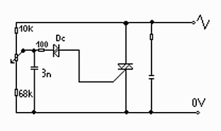
Tento triakový regulátor bol postavený za účelom otestovania funkčnosti schémy. Pred popisom zapojenia najprv trocha teórie, podľa Amatérskeho Rádia – Praktická Elektronika: „Triak je 5-vrstvová bistabilná polovodičová spínacia súčiastka určená pre spínanie striedavého napätia. Prúdom v riadiacej elektróde G je možné určiť okamžik zopnutia pri oboch polvlnách striedavého napätia. Triaky sú veľmi citlivé na spínanie prepätím t.j. nap. vyšším ako je ich max. záverné napätie (ako opatrenie je možné použiť transil podľa Amat. Radia 11/93, s.25). K zopnutiu triakov (aj tyristorov) postačí krátky impulz (jednotky mikrosekúnd) podľa A4/02, s.30.
Aby triak spínal, musí byť prekročený na zapínaciu dobu prídržný prúd. Tento prídržný prúd nie je pre obe smery vodivosti presne rovnaký a môže sa stať, že jedna polovica triaku spína nepravidelne. To vedie k vzniku jednosmernej zložky, ktorá presycuje magnetický obvod, čo zväčšuje aj striedavú zložku prúdu. Tieto javy pôsobia proti sebe a nie je ľahké nájsť príčinu. Nedoporučujem preto triaky prúdovo predimenzovávať! Podľa ARPE 1/00 str.11 (RC člen na triaku R=39J, C=10n TC342).
V článku sa dočítate
Regulátor otáčok motora 230V
Spínací obvod triaku (pre motory) by mal spínať pomocou kondenzátora, ktorý určuje akou rýchlosťou dosiahne uhol otvorenia triaku nastavenej veľkosti. Kondenzátor tak umožňuje funkciu tzv. pomalého (omeškaného) nábehu alebo mäkkého štartu (Soft-Start). Preto ak k takému regulátoru otáčok s Tc bude pripojený univerzálny motor, nemôže sa pri min. uhle otvorenia triaku roztočiť, pretože je brzdený trením. Motor sa roztočí až pri takom uhle otvorenia Tc pri ktorom je mech. trenie v motore prekonané. Táto neužitočná doba (Deadtime) môže byť v prípade potreby odstránená tým, že sa do série medzi vývody z regulačného obvodu a riadiaceho kondenzátora zapojí rezistor o vhodnom odpore (počítať s ním na DPS!). Úbytok napätia na tomto rezistore, ktorý je spôsobený prietokom prúdu posunie počiatočný uhol otvorenia Tc od nuly bližšie smerom k strednej hodnote a tým sa získa funkcia pomalého nábehu bez omeškania. Podľa ARPE Elektus 2000 str.25.
K triaku sa pripája paralelne sériový RC člen pre ochranu Tc pred napäťovými prekmitmi od motorov a pod. (100n/1kV, 180/2W) a k odrušeniu sa pred celé zapojenie vloží pí-člen s dvomi kondenzátormi 100n/1kV a tlmivkou. Podľa AR-A 2/02, str. 4.
Pre odstránenie rušenia je potrebné, aby bol triak otvorený po dobu celých periód. Podľa ARPE 2/02, str. 28. Pri záťaži indukčného charakteru, alebo dlhšom prívodnom kábli je nezbytné použiť RC člen tlmiaci napäťové prekmity, ktoré by mohli spôsobiť prieraz Tc (180/2W, 100n/1kV paral. na Tc). Podľa A1/03, str. 29. (RC obv. pre odrušenie Tc APE2/03 26 51J, 10n/630V)
Triakový regulátor zapojenie
Test triakového regulátora
Počas overovania došlo k poruche. Po rozsvietení žiarovky a regulovaní svitu zrazu niečo potichu puklo a žiarovka zhasla. Najprv som si myslel, že odišiel triak alebo diak. No bol to ochranný rezistor 100 ohm/0,25W. Preto som ho zamenil za výkonnejší a potom aj za väčší, s hodnotou 240 ohm/0,5W (ruský, ako inak….).
Ďalej by regulátor mohol byť doplnený spínačom pre vypínanie, spínačom pre spínanie „naplno“ – paralelne cez triak, aby sa zbytočne neprehrieval a poistkou, pre prípad ak by sa spálila polovica triaku a do indukčnej záťaže (motora) by šlo jednosmerne napätie (hrozí spálenie vinutia!). Tým že bude zaťaž pri vývode označenom ako fáza, a elektróda A2 (je spojená s kovovým puzdrom) bude spojená so zemou, nebude sa musieť triak odizolovávať od chladiča (kostry zariadenia). Malým prúdom, ktorý preteká cez napäťový delič a prúdom pre nabíjanie kondenzátora sa „formuje/predhrieva“ záťaž a tým sa odstraňuje impulz pri zapnutí napr.pri studenom vlákne silných žiaroviek.
Po preverení funkčnosti som začal druhú fázu testu. Jednoduché triakové regulátory nie sú vhodné pre indukčnú záťaž a tak som otestoval reguláciu na motore od starého vysávača ETA 411 500W. Ako triak bol použitý KT728/400. Niekde pred polovicou dráhy potenciometra motor naskočil a regulácia bola na v celku jednoduchý regulátor dobrá. Vhodnejší preto asi bude potenciometer 33k.
Upozornenie
Bude aj vhodne zapojiť odrušovací RC člen na triak. Ja som ho však nezapájal. Nakoniec chcem upozorniť všetkých, ktorí zapojenie budú chcieť vyskúšať, že sa pracuje so životu nebezpečným napätím a preto opatrnosti nikdy nie je dosť. Prípadné otázky adresujte na ss@stonline.sk
