Ako doplniť prijímač alebo transceiver o CW filter? Staršie továrenské zariadenia (prevažne na VKV) nemajú zabudovaný medzifrekvenčný CW filter, respektíve ho ani neumožňujú zabudovať. Tak je šírka pásma na CW určená šírkou SSB filtra, ktorá je však príliš veľká. Napriek tomu je možné takéto zariadenia doplniť o CW filter.
NF CW filter
Pomerne dobrých výsledkov môžeme dosiahnuť aj s NF filtrom. Existujú rôzne konštrukcie, ale žiadna sa jednoduchosťou nevyrovná tomuto. Využíva vlastnosti paralelného LC obvodu, ktorý sa nastavíme na požadovanú frekvenciu a pripojíme k potenciometru hlasitosti. So súčiastkami uvedenými v príklade je to cca. 800 Hz.
C1 je oddeľovací kondenzátor za detektorom. Ak je spínač S1 rozpojený, LC obvod nie je pripojený a signál sa dostáva cez potenciometer hlasitosti do NF zosilňovača bezo zmeny. Ak je spínač S2 zopnutý, signál sa dostáva na paralelný LC obvod. Z neho odoberáme signál pre NF zosilňovač. Vzhľadom k vlastnostiam paralelného LC obvodu, najvyššie napätie získame pri jeho rezonančnej frekvencii, pri iných frekvenciách bude výstupné napätie nižšie, čím sa prejaví ako bežný filter.
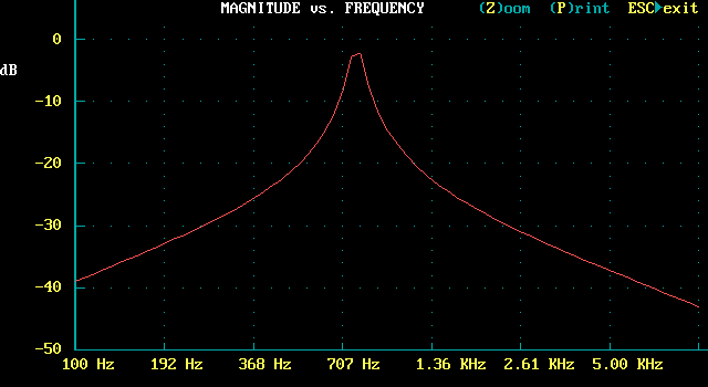
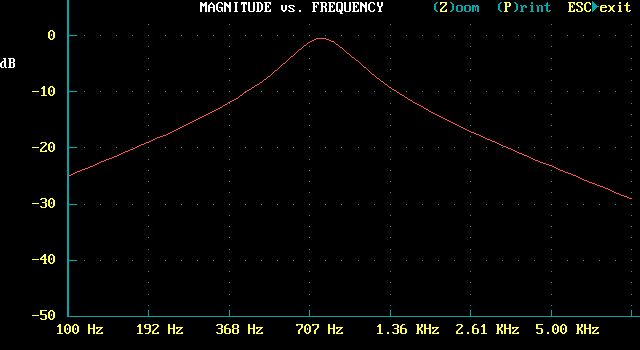
Simulácia CW filtra
Na vlastnosti takého filtra majú do veľkej miery vplyv rôzne impedancie. Už z pohľadu na schému je jasné, že potenciometer P1 znižuje Q obvodu. Ďalšou nezanedbateľnou impedanciou je impedancia detektora. Pokúsil som sa nasimulovať chovanie filtra pri rôznych impedanciách a výsledky sa rôznia, ale sú dobré aj tak.


