
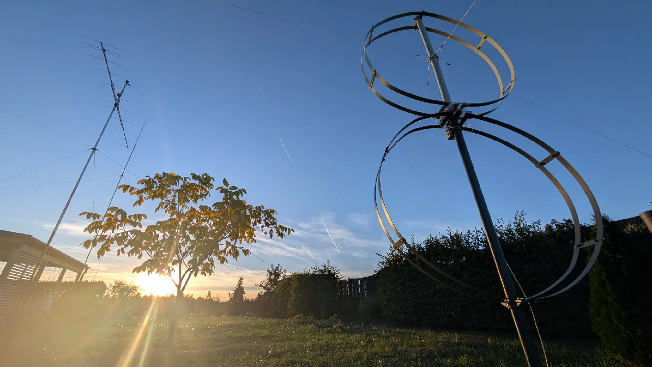
In the lower bands, the reception is often more decisive than the performance. Anyone who listens to 160 m or 80 m on a broadcast vertical antenna knows this well: high noise levels, local interference and weak signals that are lost in it. OK1HRA posted on the portal Printables enlarged version of the receiving loop antenna with amplifier LZ1AQ, intended for bands 160 m and 80 m. He also attached to the instructions a detailed comparison of the reception with the transmitting vertical antenna using signals WSPR.
You will read in the article
Active amplifier LZ1AQ
It is the heart of the structure active amplifier developed by Chavdar Levkov, LZ1AQ, from Sofia. It is intended for the construction of small broadband active receiving antennas from long waves to upper KV bands. Two loops are connected to the amplifier. It can be switched remotely between four modes: loop A, loop B, both loops crossed and connected in parallel, and dipól, pri ktorom slúžia slučky ako dve ramená malého elektrického dipólu. Prepnutie je okamžité, takže sa dá rýchlo porovnať, ktorý režim dáva na danom signáli lepší pomer signálu a šumu.
On page LZ1AQ in addition to the amplifier kit, you will also find a series of articles on broadband magnetic loops. They are devoted to protection against strong electromagnetic fields, experimental comparison of loops, the influence of height above the ground and calculation of loop parameters in the WLoop Calc spreadsheet. From November 2025 comes the modification of the AAA-1 amplifier for 45° azimuth resolution and an article about its performance on VLF and LF.
Why the bigger loop
The voltage induced in a small magnetic loop is proportional to its area and frequency. At 160 m and 80 m, the output of the loop is therefore smaller than on the upper bands, and the larger area helps to compensate for this. OK1HRA used aluminum profiles with a length of 4,640 mm. When bent into a circle, this corresponds to a diameter of approximately 1.5 m.
Material list
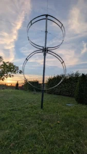
The author provides a complete bill of materials (BOM). You can buy most of the items at a hardware store or from a solid material seller, and print the rest on a 3D printer:
- 1× active amplifier LZ1AQ,
- 4× aluminum profile 40 × 4 × 4 640 mm with two holes with a diameter of 6 mm, 20 mm from the ends,
- 4× aluminum profile 40 × 4 × 200 mm with three holes with a diameter of 6 mm, 20 mm from the ends and one in the middle,
- 30× plastic tightening tape with a width of 12 mm,
- 3 m of PVC pipes with a diameter of 53 mm PN10,
- 8× screw M6 × 35 mm,
- 2× polycarbonate plate with a thickness of 10 mm and dimensions of 200 × 200 mm.
Four types of parts are printed from PETG:
- 6× spacer between aluminum profiles,
- 4x plastic pipe holder,
- 2× electronics box holder,
- 2x DIN rail holder for additional electronics.
The choice of PETG material for outdoor installation is reasonable because it withstands weathering better than PLA. It is also worth noting that the construction is done without welding and bending pipes. The entire mechanism is held together by screws and tapes.
Mechanical construction
Construction begins with the joining of aluminum profiles. Two long profiles are connected in parallel with short aluminum pieces, so that each loop is formed by a pair of parallel strips. Two plastic half-circles are attached to the center with elastic bands and two spacers on each side.
Two such assemblies are then bent into a circle and screwed to the polycarbonate sheets, creating double circles. Two more plastic half-circles are attached to each polycarbonate plate with tapes. The finished assemblies are slid onto the PVC pipe and secured with tightening tapes in four places.
Polycarbonate plates 10 mm thick serve both as an insulator and as a supporting element to which the loops are screwed. The PVC pipe is non-conductive, so the supporting structure does not affect the properties of the loop. During installation, the area that two loops with a diameter of around 1.5 m offer to the wind must be taken into account. It is therefore a good idea to fasten the tube firmly enough.
Electronics and mounting
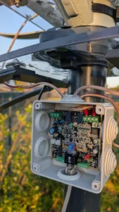
The electronics are connected according to the LZ1AQ instructions. The electronics box has its own integrated plastic holders that are part of the 3D printed parts. DIN rail holders are available for additional electronics, such as control or power supply.
Since the amplifier supports switching between loops A and B, the two loops can also be used directionally. When receiving on the lower bands, it is especially practical when you need to suppress interference from a certain direction or a strong station near the desired frequency.
Comparison of reception via WSPR
The most interesting part of the project is the income comparison. Included in the downloads is an HTML file with an exact comparison of the reception between the transmitting vertical thirty-radial antenna and the receiving loop based on the reception of WSPR beacons on the 80m band.
Screenshot from the tool WSPR Antenna Lab, exportovaná 16. októbra 2026, zachytáva príjem na 80 m v reláciách od 11. októbra 16:40 UTC until October 16 06:40 UTC. Two-minute WSPR cycles with a matching tolerance of 5 Hz were compared. Spots that were not confirmed by the WSPR database and segments in which one of the antennas did not receive anything were excluded. The results say clearly:

- number of spots: loop 3,912, vertical 3,177, i.e. 735 more in favor of the loop,
- joint broadcasts: 3,058, of which only 854 were captured by loop and only 119 by vertical,
- higher SNR on the same broadcast: loop in 2,879 cases, vertical in 95, coincidence in 84 cases,
- average SNR difference: +5.2 dB in favor of the loop, median +5 dB,
- average SNR on co-transmissions: −13.2 dB against −18.4 dB,
- various stations: 120 vs. 115, exclusively captured 7 vs. 2,
- DX spots over 3,000 km: 36 against 34, farthest spot 8,279 km for both antennas.
In the overall evaluation, the loop came out better in six criteria, the vertical in two and two criteria were equal. The vertical had more very weak spots with an SNR of less than −20 dB (1,619 vs. 1,459) and a slightly higher median distance (1,230 km vs. 1,147 km). The tool itself warns that the criteria are not independent and the total score is only indicative.

At 80 m, the receiving loop showed a clear advantage. On 160 m and 40 m, this advantage was not confirmed, but the results could be different when compared with another transmitting antenna.
This note is important. The comparison applies to a specific transmit antenna at a specific QTH. Those who have a good broadcast antenna on 160 m with an extensive radial system may not achieve the same difference with a loop. If, on the other hand, you struggle with local interference, the result can be even more pronounced.
Video: active LZ1AQ loop in practice
A video from the Tech Minds channel shows how the active magnetic loop with the LZ1AQ amplifier looks in practice.
Model license and origin
The author marked the model as his own original work and distributes it under the Creative Commons Attribution-ShareAlike 4.0 International license. So you can freely modify, distribute and commercially use the model as long as you credit the author and publish derivative works under the same license. Download files can be found on the site LZ1AQ RX loop antenna on Printables.
Conclusion
OK1HRA's enlarged receiver loop combines the proven LZ1AQ amplifier with a simple mechanical construction made from off-the-shelf material and a few 3D printed parts. Its biggest asset is the comparison with a real broadcasting antenna instead of the subjective impression "he hears it better". On 80 m, an average gain of more than 5 dB SNR on the same transmissions proves that a separate receiving antenna makes sense even on a smaller plot. Anyone looking for a better income in the lower bands has a complete guide and materials for their own comparison at their disposal.