
Moderné rádioamatérske Today's workplace often consists of a classic HF transceiver supplemented by a separate SDR receiverSuch a configuration allows simultaneous monitoring of the entire band, more efficient search for DX stations, monitoring of contest frequencies or program operation. CW skimmer. Spoločným problémom však zostáva bezpečné pripojenie oboch zariadení na jednu anténu.
When transmitting, the power output at the antenna connector of the transceiver is in the order of tens to hundreds of watts. If SDR receiver connected directly in parallel to the antenna, it must be immediately damaged or its parameters must deteriorate significantly. It was designed to solve this situation LZ1AQ TRX-SDR Switch , which automatically switches the common antenna between the transceiver and the SDR receiver while ensuring protection of the sensitive SDR input during transmission.
In the article you will read
When is it necessary to use a TRX-SDR switch?
The TRX-SDR switch is designed primarily for stations that want to use a separate SDR receiver together with a classic transceiver on a single antenna. A typical example is contest operation, where the SDR receiver displays the entire band, while the transceiver operates on only one frequency.
Prepínač nájde uplatnenie aj pri bežnej DX prevádzke. operátor can use an SDR receiver to monitor activity on the band, search for new stations, or check frequency occupancy without the need to switch the receiver in the transceiver.

RF path (orange): Antenna → ANT Switch (ANT port) → TRX port → Transceiver, and RX port → AF Switch board → SDR receiver
Control (green): SPST switch → CTRL port of ANT Switch
12 V power supply (red): Napájací zdroj → ANT Switch aj AF board
PTT (red intermittent): Transceiver → ANT Switch
Audio (blue): Transceiver ↔ AF board ↔ Headphones; SDR → PC (USB)
Another common application is the use of CW Skimmer or SDR Console software. In these cases, the SDR receiver does not operate as a stand-alone radio station, but as a panoramic receiver displaying the entire band in real time. Automatic disconnection during transmission is necessary to protect the input circuits of the SDR receiver.
Why isn't a regular antenna splitter enough?

Simple passive antenna signal distribution using a T-connector or power splitter is not a suitable solution. During transmission, the entire transmission power is also fed to the input of the SDR receiver. Most SDR receivers are designed for signal levels in the microvolt to millivolt range.
The TRX-SDR switch therefore connects the antenna to both receivers during reception according to the selected mode, while when the PTT is activated, it immediately disconnects the SDR receiver from the antenna and connects it exclusively to the transceiver. The whole process is automatic without operator intervention. The technical solution is designed so that the switchover takes place before the start of transmission and at the same time the return to the receiving mode takes place only after the transmission is completed. This minimizes the risk of power leakage into the SDR receiver.
Main features of the LZ1AQ switch
The LZ1AQ switch was designed specifically for amateur radio stations using a separate SDR receiver. It is not just a simple relay switching the antenna, but a device that coordinates the switching of the antenna path, PTT signal and other control inputs according to the chosen connection method.
The manufacturer supports multiple ways to activate the switch. The switching can be controlled using the transceiver's PTT output, a signal from a power amplifier, or other compatible control circuits. This allows the switch to be integrated into both simple and more complex contest setups, including workstations with an external power amplifier.
Great attention has also been paid to operational safety. The control logic ensures the correct switching order of individual relays so that the SDR receiver is disconnected before the start of the broadcast and reconnected only after it has ended. This principle significantly reduces the risk of damage to sensitive input circuits.
Construction and principle of operation
The device is based on high-frequency relays with a controlled time sequence of switching. During reception, the antenna is connected to both the transceiver and the SDR receiver according to the selected operating mode. After activating the PTT, the control electronics first disconnects the SDR receiver from the antenna and only then connects the antenna to the transceiver's transmitting branch.
After the transmission is finished, the entire process is performed in reverse order. First, the transceiver transmission is stopped and only after a defined delay does the SDR receiver reconnect to the antenna. This eliminates the risk of switching while high-frequency power is present.
Such a solution is especially important in digital modes of operation or contexts where switching between transmission and reception occurs very frequently and in short time intervals.
First commissioning
LZ1AQ recommends performing a basic functional check according to the service documentation before connecting the transceiver for the first time. This includes verifying the correct operation of the relay, checking the power supply and correct switching when activating the PTT. Only after successfully verifying the functionality is it recommended to connect the SDR receiver and then the transceiver.
It is equally important to verify the correct PTT polarity and control method for the specific transceiver type. The manufacturer lists several connection options in the documentation depending on the device used, and correct configuration is a basic prerequisite for reliable operation.
Video: Introducing the LZ1AQ TRX-SDR Switch
LZ1AQ links to practical examples of connection and commissioning of the switch on its website. Before assembly, it is worth watching the videos dedicated to connection, configuration and functional tests, which supplement the technical documentation. This kit is no longer produced, but the complete documentation is available at https://sdrswitch.active-antenna.eu/wp-content/uploads/2024/02/trx-sdr-switch-lz1aq-sources.7z and manual in PDF https://sdrswitch.active-antenna.eu/wp-content/uploads/2020/10/trx-sdr-switch-lz1aq-v1.7. 2.pdf
How does the TRX-SDR switch connect?
The LZ1AQ TRX-SDR Switch consists of two separate modules – the antenna switch (ANT Switch) and the control module (Audio Switch). The antenna module is placed as close as possible to the antenna connector of the transceiver to keep the high-frequency connecting wires as short as possible. The control module provides PTT signal processing, audio path switching and antenna relay control.
The basic connection uses a common antenna for both the transceiver and the SDR receiver. The control signal is the standard PTT output of the transceiver, labeled by the manufacturer, for example, SEND, TX-GND, T/R LINE or Ground-on-Transmit. After activating the PTT switch, the SDR receiver is first disconnected from the antenna, then connected to the transmitting branch and switched the audio to the transceiver. After the transmission is completed, the switching is performed in the opposite order, while the return of the audio from the SDR can be timed according to the software and receiver used.
Use with a power amplifier
If an external power amplifier (PA) is used in the setup, the manufacturer recommends adhering to the precisely defined wiring. The reason is a protection function called TRX PTT missing protection. If connected incorrectly, the control module may be grounded via the power amplifier even if the PTT cable is disconnected. The switch would then incorrectly evaluate the status as receiving and the SDR would remain connected to the antenna when transmitting.
Proper wiring ensures that when the PTT wire is disconnected, the switch remains in a safe transmitting state, minimizing the risk of damage to the SDR receiver. The manufacturer therefore recommends paying increased attention to the grounding method and routing of the PTT wires, especially in contest workstations with multiple devices.
Technical parameters of LZ1AQ TRX-SDR Switch
| Parameters | Value |
|---|---|
| Power supply | 10 to 15 V DC |
| Maximum withdrawal | 55 mA at 13.6 V (without external relay) |
| SWR during broadcast | < 1.2 in the range 1.8 to 50 MHz |
| Attenuation at TRX input (RX) | approximately 2.5 dB |
| SDR input attenuation (RX) | approximately 3.5 dB |
| Switching delay after PTT activation | 3ms |
| Delay in returning to RX | 5ms |
| Adjustable audio switching delay | 10 to 700ms |
| External relay control | 12V / max. 200mA |
The switch incorporates multiple protection features including a resettable power fuse, PTT wire disconnection protection, antenna switch disconnection protection, and multiple relay failure protection. The SDR input limiter can limit the RF signal level to a safe level in the event of a fault, and also includes a resistor fuse that acts as a sacrificial element protecting the receiver input under extreme loads.
Resolving ground loops
When using an SDR receiver connected to a computer, the problem of ground loops often arises. The computer, SDR receiver and transceiver may be powered from different sources and connected by multiple cable shields. The result is increased noise, interference or the creation of unwanted currents between individual devices.
The LZ1AQ TRX-SDR Switch design solves this problem by galvanically isolating the audio paths and using a broadband transformer along with common mode chokes on the control and power wires. This significantly reduces the occurrence of ground loops without negatively affecting the high-frequency characteristics of the entire setup.
LZ1AQ also recommends powering the switch from the same 12 V source as the transceiver. A common ground reference reduces the likelihood of potential differences between devices and contributes to more stable operation.
Video: CW operation with SDR-TRX switch
Summary
The LZ1AQ TRX-SDR Switch is a well-thought-out solution for radio amateurs who want to safely combine a classic transceiver with a standalone SDR receiver. In addition to antenna switching itself, it ensures correct relay timing, SDR input protection, audio path switching, and the possibility of integration with an external power amplifier. An important part of the design is also the solution of ground loops and protection mechanisms that increase the reliability of the entire set. Thanks to openly published documentation and detailed assembly instructions, this is an interesting project for designers and experienced radio amateurs building a modern SDR workplace.
Je třeba o něčem psát.
LZ1 by mohl uvést typ a útlum relátek. Jejich konfigurace, seriově a paralel?
Většina lidí nemá možnost měřit útlum -40dB nebo -60dB. Sám jsem naměřil -51dB na 30MHz. Z obyčejných relé byly dobré NEC pro telefonní služby s 10 miliony cyklů.
Relé se zdá jednodušší řešení než PIN, který chtějí větší závěrné napětí, časování. A pak závěrné napětí vyrobit & aby nerušilo. KX3 to má udělané s odřenýma ušima.
Tento kit sa už nevyrába, ale kompletná dokumentácia je k dispozícii na https://sdrswitch.active-antenna.eu/wp-content/uploads/2024/02/trx-sdr-switch-lz1aq-sources.7z and manual in PDF https://sdrswitch.active-antenna.eu/wp-content/uploads/2020/10/trx-sdr-switch-lz1aq-v1.7.2.pdf
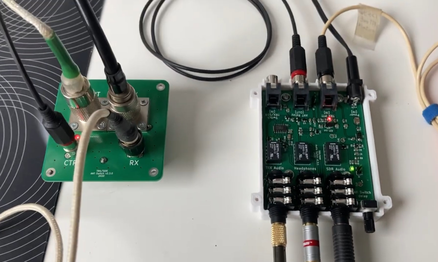
Z obrázkov je vidieť relé ZETTLER AZ850- 12 v audio a Panasonic TQ2SA-12V vo VF prepínači. Strana 22 dokumentácie obsahuje aj zjednodušené schéma prepínania a ochrany vo VF ceste. Datasheet pre toto relé uvádza izoláciu -50dB na 30 MHz, ale na 100W výkonu by bolo vhodné hľadať trocha robustnejšie relé.
Napríklad https://antennas-amplifiers.com/cheap-high-power-50-144-mhz-relay-with-n-connectors/ , ktoré je použiteľné na KV aj VKV.