Robert S53WW je skvelý konštruktér zariadení na VKV. Na jeho stránkach nájdete napríklad aj popis sústavy antén na 2m vhodnej do contestov a kvalitného transvertoru Javornik 144/14MHz. Poprosil som ho o súhlas na preklad a publikovanie týchto článkov. Robi mi ho obratom zaslal, za čo mu patrí veľké ďakujem. Postupne Vám ich všetky prinesieme na www.CQ.sk . Ak sa Vám ale nechce čakať, navštívte jeho stránky http://lea.hamradio.si/~s53ww/.
V článku sa dočítate
Úvod
Po dôkladnej analýze rôznych predzosilňovačov pre môj nový 144/14 MHz transvertor som nakoniec ostal pri Infeon BF998 MOS-FET-e. Mal som veľmi dobré skúsenosti so starou BF-981 a tak som začal testovať BF998. Tento tranzistor je lacný, ľahko dostupný a má veľmi dobré charakteristiky. GaAs FET som nepoužil, pretože sú ťažko dostupné a drahé, pričom rozdiely sú minimálne.
Z analýzy transvertoru bolo jasné, že výslednú odolnosť celej zostavy určuje predzosilňovač (ak využívate +17dBm zmiešavače s oscilátorovým signálom +20dBm a za ním zosilovač s IP3 out > 36dBm a zanedbávate odolnosť KV TCVR)! OK, komerčné KV prijímače by nemali mať odolnosť zlú (IP3 in < +15dBm až +25dBm, AOR-7030 až +30dBm). V tomto prípade má byť IP3 out minimálne na tejto úrovni (+30dBm). Šum KV prijímačov sa pohybuje na úrovni 16dB, v lepšom prípade okolo 13dB.
Ak odhadneme stratu v koaxiálnom kábli ANT-XVRT asi na 0,5dB a budeme požadovať výsledné šumové číslo okolo 2,2dB, zistíme, že zisk XVRT musí byť minimálne 24dB (so šumovým číslom 1dB). Z toho vyplýva, že IP3 in musí byť viac ako +6dBm (=30dBm-24dB). Splniť túto požiadavku nie je jednoduché práve kvôli predzosilňovaču.
Nízkošumový predzosilňovač s paralelnou kombináciou n-krát BF998
Pokus osadiť pôvodný predzosilňovač novou BF998 nepriniesol výrazné zlepšenie. Mal zisk 26,5 dB, šumové číslo 0,8 dB, P1dB 17 dBm a IP3 in 0 dBm. Nie sú to zlé hodnoty, ale mohli byť aj lepšie.
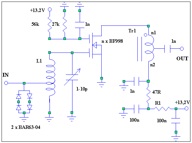
Na prvom obrázku je bežné zapojenie predzosilňovača s dvojbázovým MOSFET s ohľadom na maximálny zisk. Idss sa nastavuje na minimálnu úroveň šumu (Idss je udávaný v rozsahu 2 až 18mA – zvyčajne býva medzi 10 až 15mA). Vstupná cievka L1 je vinutá na priemere 5mm 1,0mm AgCu drôtom; má 6 závitov s dĺžkou vinutia 11mm. Mala by byť umiestnená minimálne 2mm nad zemou a prinajmenšom 10 mm od kovových častí krabičky. Kapacitné trimre musia byť kvalitné. Diódy (Infineon BAR63-04 nebo BAR64-04 nebo BAR14-1) slúžia na ochranu MOSFET. Nemajú takmer žiadny vplyv na šumové číslo ani odolnosť, ich požitie v reálnych podmienkach je žiadúce. Najkritickejšou časťou je transformátor TR1: mal by byť navinutý na dvojotvorovom jadre veľkosti A7 z materiálu U17 (Epcos, predtým Siemens&Matshushita). Materiály iných výrobcov môžu byť použité s ohľadom na zhoršenie zisku a P1dB. Trifilárne navinieme dva závity – je to vždy lepšie ako autotransformátor so 6 závitmi (=2×3) primárneho vinutia a odbočkou na druhom závite od studeného konca (v praxi sa navinú najprv 4 závity, skrútením vodičov sa vytvorí odbočka a dovinú sa ešte 2 závity). Vývody TR1 je nutné skrátiť na 5mm a viesť ich v blízkosti zeme na plošnom spoji, ináč sa môžu vyskytnúť oscilácie na vysokých frekvenciách.
Pri experimentovaní som našiel zaujímavé zapojenie FET (používané v NF zosilňovačoch), kde paralelne spojené dva identické FET-y majú nižší šum ako jeden! Takže ak vyberiete ďalšiu BF998 (musí mať rovnaký Idss, nutné vybrať), môžete sa dostať až na hodnotu 0,6dB NF, zisku 26,5dB a rovnaký alebo horší (!?) IP3 in. Problém s IP3 je vyriešiť vhodnejším prispôsobením výstupu – miesto transformátora s pomerom 3:1 použijeme 2:1. Týmto spôsobom dosiahneme +28,5dBm výkonu IP3 (P1dB je +19dBm). Všeobecné zapjenie LNA n-krát BF998 je na ďalšom obrázku (dosiahnuté hodnoty sú uvedené v tabuľke).

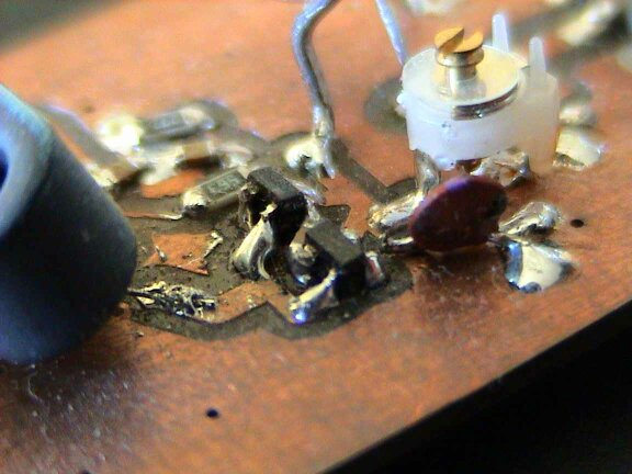
Samozrejme som vyskúšal aj štvoricu BF998 (kto by nechcel) – šumové číslo sa zníži na 0,5dB, zisk ostáva 26,5dB (pri nastavení na minimálne šumové číslo) a IP3 out je +34dBm. Na dosihnutie tejto hodnoty IP3 je nutné zmeniť pomer TR1 na 1,3:1. Odbočka L1 je v strede vinutia (na treťom závite). Pri prvom pokuse zosilňovač zakmitával nad 3,5GHz, čo ale nevplývalo na 2m. Vyskúšal som umiestniť po dvojici tranzistorov na každú stranu plošného spoja prepojených krátkymi drôtikmi a oddelenými obvodmi predpätia G2 (rozmiestnenie súčiastok a blokovacieho kondenzátora je kritické). Po tejto úprave kmitanie zmizlo, ale rád by som poznamenal, že všetky zapojenia sú iba za určitých podmienok stabilné. Rozmiestnenie súčiastok je kritické, najmä sa to týka blokovacieho kondenzátora 1nF.


Schéma zapojenia predzosilňovača n-krát BF998 (podobný ako s jednou BF998). Hodnoty premenlivých súčiastok nájdete v tabuľke. Aj prisposobenie vstupu a výstupu je rôzne (viď.text). Materiál transformátora je zhodný ako v predošlom prípade, pri požití viacerých BF998 odporúčam veľkosť A4. Predzosilňovače môžeme naladiť bez meracej techniky malým trikom na minimálne šumové číslo: naladíme ich na maximálny zisk na 136 MHz (šumové číslo sa takmer nemení v širokom rozsahu).
Tu si môžete stiahnuť nákres plošného spoja ftp://lea.hamradio.si/pub/vhfct/lnaa2.zip.
|
n1 |
n2 |
R1 |
NF [dB] |
T [K] |
G [dB] |
IP3in [dBm] |
P1db [dBm] |
|
|
1 x BF998 |
4 |
2 |
150 |
0,8 |
61 |
26,5 |
0 |
17 |
|
2 x BF998 |
2 |
2 |
100 |
0,6 |
44 |
26,5 |
2 |
19 |
|
4 x BF998 |
1 |
3 |
10 |
0,5 |
36 |
26,5 |
7 |
23 |

Push-pull LNA s BF998

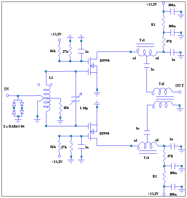
Push-pullový zosilňovač sa ziskom vyrovná dvojstupňovému jednoduchému zosilňovaču a IP3 je asi o 3dB lepší ako v prípade paralelnej konštrukcie. Vyskúšal som zapojiť teda dvojicu BF998 do push-pullu. Prvé výsledky boli výborné: IP3 inbolo +6 dBm (P1dB +23 dBm), ale šumové číslo bolo minimálne 1,3dB! Po zmene vstupného obvodu som dosiahol šumové číslo 0,9-1,0dB, IP3 out 32,5dBm pri zisku 26,5dB (nastavenie na minimálne šumové číslo). Výsledné zapojenie je spojením dvoch jednostupňových zosilovačov podľa prvého obrázka.
Push-pullové zapojenie dvoch BF998. Vstupná cievka L1 je navinutá na priemere 11mm drôtom 1,0mm AgCu; má 4 závity a dĺžka vinutia je 7mm. Väzobná cievka má 1 závit na rovnakom priemere ako L1 smaltovaným Cu drôtom tak, že nemôže skratovať L1. Transformátory TR1 a TR2 sú na zhodnom materiále ako jednoduchý LNA (veľkosť A7, materiál U17, Epcos). Výstupný transformátor TR2 má dva závity bifilárne.
Potom som sa ešte pokúsil o push-pullové spojenie štvorice BF998. Zámerom bolo dostať IP3 in okolo +9dBm pri šumovom čísle asi 0,8dB. Aj keď IP3 in som dosiahol podľa predstáv, v mojich silách nebolo dosiahnuť želané šumové číslo. To bolo stále vyššie ako 1,3dB, čo sa mi zdalo nevhodné ku XVRT. Pre iné účely môže ale táto hodnota vyhovovať, žiada si to ešte experimentovanie.
Upozornenie:
Tieto predzosilňovače nie sú vhodné na priame pripojenie pred prijímač alebo transvertor pretože majú veľmi vysoký zisk. Ich efektívne využitie (aj keď ja neodporúčam používať predzosilňovače) je možné s útlmovým článkom na ich výstupe, čo zníži zisk. Vo väčšine prípadov 6-10dB zisku je dostatočné na predzosilňovač, ak skutočne musí byť použitý. S útlmovým článkom -20dB sa celkové šumové číslo zhorší z 0,5/0,6/0,8dB na 1,3/1,4/1,5dB. S útlmovým článkom -16dB sa celkové šumové číslo zhorší z 0,5/0,6/0,8dB na 0,8/0,9/1,1dB. Takže odporúčam Vám za predzosilňovačom používať atenuátor -16dB (hodnoty pí-článku sú 68 ohmov voči zemi a 150 ohmov medzi nimi).
Vysokokvalitné VHF a vyššie predzosilňovače nájdete na stránkach Dragana YU1AW: www.QSL.net/yu1aw/low_noise.htm.
Do septembra 2002 som postavil šesť predzosilňovačov s so šumovým číslom 0,5-0,6dB (BF998 Philips, označené Mop) a tri so šumovým číslom 0,8-0,9dB (BF998 Infeon, označené Mos). Zlé správy sú, že Epcos prestal distribuovať materiál U17 a je teda veľmi ťažké zohnať dvojotvorové jadrá U17/A4. Nie je zatiaľ známa ich náhrada, ale jadrá podobnej veľkosti z materiálu s permeabilitou medzi 20-30 sú použiteľné…
Po premeraní deviatich predzosilňovačov odporúčam jednoduchý spôsob na nastavenie LNA 4xBF998 na minimálny šum: nalaďte trimer C na maximálny zisk, potom zvyšujte jeho kapacitu, kým zisk nepoklesne o 1dB! Naladenie nie je kritické, vstupný obvod je širokopásmový pri nastavovaní minimálneho NF (asi 10 MHz).
Robi, S53WW
http://lea.hamradio.si/~s53ww/
Preložil a upravil so súhlasom autora Viliam, OM3-0122