Autorom tohto veľmi vydareného projektu je Mak, SV1BSX (https://www.QSL.net/sv1bsx/).
V článku sa dočítate
O aktuátoroch
Za týmto nie moc obvyklým slovom sa ukrýva zariadenie, ktoré snáď každý už videl. Používa sa na natáčanie SAT TV parabol. Je to ruka (v angličtine sa zvykne označovať aj arm – ruka), čiže lacné, ale pevné a silné zariadenie predurčené na ovládanie anténnych systémov. V nasledujúcich riadkoch vnikneme do tajomstiev aktuátorov.

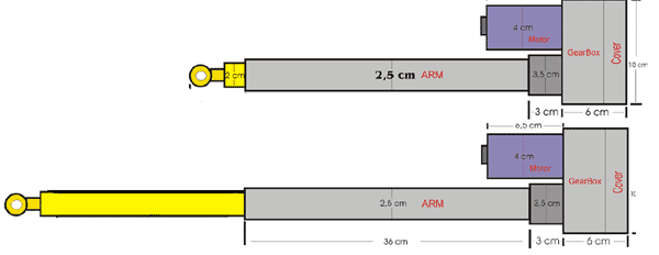
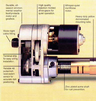
Na trhu sú aktuátory vytláčané modernejšími systémami DiSEq dodávanými ku digitálnym prijímačom. Vo výpredajoch tak možno kúpiť za lacný peniaz (cca. 1000,-Sk) solídny aktuátor. Napájacie napätie sa rôzni, pre nás sú najvhodnejšie aktuátory s napájacím napätím 12V, alternatívne aj 18V (motor bude mať menšie otáčky, slabší záber na 13,8V). Dôležitým parametrom je zdvih aktuátora udávaný v palcoch. Je to maximálna dĺžka vysunutia ramena. Bežne predávané aktuátory sú od ôsmich do tridsiatich šiestich palcov (20 – 92cm). Na obrázku č.2 je nakreslený 12-palcový rotátor aj s rozmermi, na obrázku č.3 funkcia.

Ako to pracuje?
Ako už bolo spomenuté, aktuátor sa skladá z motora na jednosmerný prúd, prevodov a skrutkovnice, ktorá premieňa kruhový pohyb na priamočiary. Takže, keď na aktuátor privediete napätie, rameno sa začne vysúvať a po zmene polarity zasúvať.
Motory potrebujú napätie v rozmedzí 12 až 36V. Ja som použil 36V model. Pri vyššom napätí je tak prúd oveľa menší (detaily v časti napájanie). Motor sa však točí aj pri 12V, ale oveľa pomalšie. Je to vhodné na drobné korekcie, zvlášť pri satelitoch na vyššej obežnej dráhe a užších vyžarovacích uhloch antén. V praxi sa mi osvedčilo napätie medzi 12 až 24V, pri 36V je rýchlosť už príliš veľká.
Napájanie
Ako už bolo spomenuté, nominálne napätie aktuátorov sa pohybuje od 12 do 36V. Ak máte aktuátor na 12V, môžete využiť aj zdroj 13,8V, z ktorého napájate transceiver.
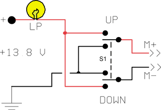
Vo chvíli, keď sa aktuátor rozbieha je prúdová špička dosť vysoká. Rozbehový prúd je niekedy až 5 až 10-krát vyšší ako nominálny! Zamedzenie týchto špičiek je jednoduché – zaradením žiarovky do napájacieho prívodu. Vytvorí sa tak najjednoduchší obvod „soft-startu“. Hodia sa na to autožiarovky nad 5W. Vhodnú je potrebné vybrať skusmo podľa nasledujúceho postupu: ako prvú zapojte 5W žiarovku a zapnite napájanie. Ak žiarovka aj po rozbehu naďalej svieti, budete potrebovať silnejšiu. Ideálne je, keď pri štarte žiarovka blikne a potom nesvieti, alebo len žne. K dvanásťvoltovému aktuátoru sú vhodné žiarovky na 6 až 12V, k dvadsaťštyrivoltovému 12 až 24V.
S1 je dvojitý ON-OFF-ON prepínač. V strednej polohe je v polohe OFF – vypnutý. Krajné kontakty sú využité ako UP (hore) a DOWN (dole). Prepnutím S1 do polohy UP sa na motor privádza napätie jednej polarity, v polohe DOWN opačnej. Tak sa rameno aktuátora buď vysúva alebo zasúva.
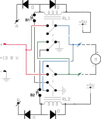 Na obrázku č.6 je rozšírené ovládanie rotátora umožňujúce manuálne aj diaľkové ovládanie. Tlačidlami B1 a B2 ovládame aktuátor manuálne. Diaľkové ovládanie sa realizuje uzemnením bodu A alebo B, napríklad cez výstupný tranzistor elektronického obvodu (napríklad FodTrack a pod.). Takto je možné aktuátor ovládať z počítača, či už na pokyn obsluhy, alebo automaticky z predikčného programu.
Napríklad, ak je uzemnený bod A, relé RL1 pritiahne, na motor sa dostáva napätie, rameno sa vysúva, elevácia sa zvyšuje. Uzemnením bodu B sa dej reverzuje.
Diódy D sú ľubovoľné kremíkové alebo diódy ako 1N4003, 1N4004 a pod.
Obvod vyzerá síce zložito, ale to len preto, že je „blbuvzdorný“. Značí to, že ak je zopnuté relé RL1, nemôže byť zopnuté relé RL2 a opačne. Rovnako, ak by z akéhokoľvek dôvodu došlo ku súčasnému stlačeniu tlačidiel B1 a B2, iba jedno relé bude zopnuté. Inak by sa mohlo stať, že vyskratujete zdroj!
Možnosť diaľkového ovládania je užitočná, ak ovládate aktuátor z počítača. Napríklad s rozhraním Fodtrack a týmto obvodom s relé je možné riadiť akýkoľvek aktuátor (Fodtrack piny č.3 na A pin 5 na B). Naznačené napájacie napätie relé 5V je len ako príklad. Volíme ho podľa typu použitých relé. Hlavne majte na pamäti, že obvod môžete prispôsobiť a zmeniť podľa svojich potrieb.
Použitie žiarovky ako obvodu „soft startu“ je jednoduché a efektívne. Ale ak chcete použiť sofistikovanejšiu metódu, alebo váš aktuátor nemá napájacie napätie 12V, potom je potrebné zhotoviť nezávislý napájací zdroj.
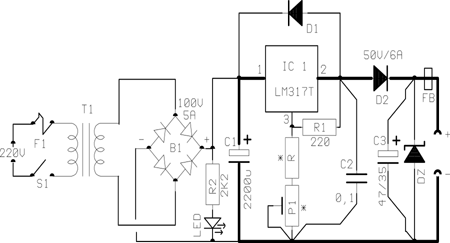
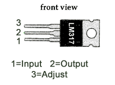 LM317T má veľkú výhodu ako napájací zdroj pre tento účel, pretože obsahuje prúdový obmedzovač. Takže maximálny výstupný prúd je 1,5A a obvod so žiarovkou nie je potrebný. Navyše trimrom P1je možné nastaviť vhodné výstupné napätie k aktuátoru od 12 do 36V.
LM317T je jednoduchý trojvývodový stabilizátor s výstupným prúdom do 1,5A a výstupným napätím medzi 1,2 až 37V. Obsahuje obmedzovač prúdu a teplotnú poistku. Vstupné napätie musí byť minimálne o 3 až 4V vyššie ako výstupné, ale nesmie presiahnuť 40V. Výstupné napätie je určené deličom R1, R2 (v schéme na obr.7 platí, že R2 = R+P1). Pre výstupné napätie v rozsahu 8 až 13,8V je R 1k2, P1 1k, pre výstupné napätie 11,5 až 24V je R 1k8 a P 2k2
Hodnoty rezistorov v deliči je možné vypočítať podľa vzorca:
Vout = 1.25 * ( 1 + R2 / R1 )
Pretože je ako R2 použitá kombinácia trimra P1 a pevného rezistora R, je delič čiastočne premenný a umožňuje tak variovať výstupné napätie. Je dôležité pamätať na to, aby ani pri plnom odbere nepokleslo vstupné napätie do stabilizátora oproti výstupnému pod 3V, radšej 4V. Vzhľadom k tomu je treba dimenzovať transformátor.
Zapojenie je rozšírené o obvody potlačujúce prechodné javy vznikajúce na indukčnej záťaži, ako motor aktuátora určite je. Navyše, od zdroja vedú pomerne dlhé káble, ktoré sa tiež prejavujú ako indukčnosť. Aby LM317-ka pracovala spôľahlivo, je potrebné pridať Zenerovu diódu, blokovací kondenzátor C3 a feritovú perlu.
Zenerovo napätie diódy musí byť o 4 až 5V vyššie ako je maximálne výstupné napätie zdroja. Napríklad, ak je výstupné napätie zdroja 12V, potom DZ má byť na 16V/1W.
Zapojenie má ešte jednu východu – ak sa ako P1 použije potenciometer, je možné kedykoľvek znížiť napätie a tak dosiahnuť pomalší pohyb antén a presne tak dokorigovať malé odchýlky v elevácii.
Koncové vypínače (horný a dolný)
Aktuátory majú dva nastaviteľné koncové vypínače vo vnútri prevodovej skrinky. Nimi je možné nastaviť spodný (na 0°) a horný (na 90°) doraz. Je to dôležité aj z hľadiska ochrany samotného aktuátora, ktorý by sa mohol pri presahu a nadmernej záťaži poškodiť.
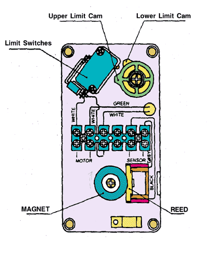
Správnym nastavením koncových vypínačov sa bude celý systém bezpečne elevovať v rozsahu 0 až 90 stupňov. Napríklad, ak aktuátor dosiahne horný alebo dolný vypínač, ten odpojí napätie od motora. Bude reagovať len na napätie opačnej polarity, ktoré znamená bezpečný pohyb.
Na stránke http://www.qsl.net/sv1bsx/actuator_lnk.html sú podrobné informácie od výrobcu SATENG. Dostal som email od rádioamatéra, ktorého aktuátor nemal dorazové vypínače. Nemám predstavu ako je to možné, je však nemysliteľné aby výrobca nezabudoval tieto časti do aktuátora. Určite tam teda budú, ale nie sú nastaviteľné.
Majte na pamäti, že rozsah elevácie aktuátora je od 0 do 90 stupňov, kým originálne elevačné rotátory umožňujú aj preklopenie rotátora, čiže eleváciu v rozsahu 0 až 180 stupňov (flip mode).
Takže, ak je oblet satelitu nadhlavníkový, aktuátorový systém neumožňuje sledovať jeho pohyb bez prerušenia. Antény od AOS (objavenia satelitu nad obzorom) zdvíhame až po 90 stupňov, potom azimutálnym rotátorom otočíme antény o 180 stupňov a sklápame ich až po LOS (strata satelitu za obzorom). V praxi je však nadhlavníkových obletov relatívne málo. Vhodným riešením sa dá dosiahnuť rozsah elevácie až do 135 stupňov. Ba teoreticky je možné pomocou piestu (na podobný spôsob ako v motore auta) dosiahnuť aj plnú eleváciu Toto však nemá v praxi veľký význam…. , keďže nadhlavníkových obletov je len 1 až 2% a antény majú dostatočnú šírku vyžarovacích lalokov.
Spôsob odčítania veľkosti elevácie
Riadiace jednotky k TV satelitným prijímačom využívajú impulzné odčítanie veľkosti vysunutia aktuátora. Je to zvyčajne 48 pulzov na 1 palec (2,54 cm). To obvody v prijímači prevedú na stupne, ktoré sa zobrazia na displeji.
Pre rádioamatérske použitie tento spôsob prináša značné komplikácie. Väčšina satelitných trackingových interfaceov, ktoré umožňujú ovládať rotátor má napäťový vstup na zistenie veľkosti elevácie. Takže tento problém treba vyriešiť. Ako prvá možnosť sa ponúka skonštruovať podobný systém ako je v satelitnom príjímači, napríklad s PIC a digitálnou stupnicou. To si však vyžaduje znalosti týchto obvodov, a to nemá každý.
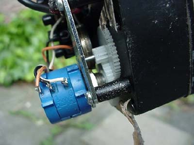
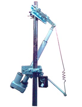
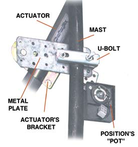
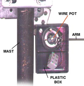
Ale existuje ešte jednoduchá pomoc: potenciometer mechanicky spojený s aktuátorom. Je to možné viacerými spôsobmi urobiť. Jednou z nich je preniesť moment cez kladku na osku potenciometra. Ako druhá možnosť je použiť jednoduchý pákový systém. Inšpirácie ako na to sú na obrázkoch. Veľmi pekný patent však vymyslel PA4FP. Zabudoval viacotáčkový potenciometer priamo do skrinky aktuátora a ozubeným kolieskom z detskej hračky ho naviazal do prevodu od motora.
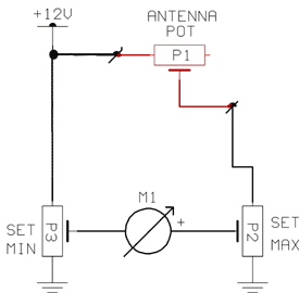 Na obr.9 je jednoduché zapojenie, ktoré umožňuje na stupnici meracieho prístroja odčítať eleváciu priamo v stupňoch. Ak je dobre nakalibrované, presnosť je 1 stupeň. Červenými čiarami v schéme sú nakreslené časti, ktoré sú mimo shacku. Ako vodiče k potenciometru stačí bežná dvojlinka (2 x 0,5 mm).
P1 má 5k, triemer P2 tiež 5k. Trimer P3 má 10k, všetky priebehy sú lineárne. Je výhodné, aby P2 a P3 boli viacotáčkové typy, ľahšie sa tak systém kalibruje. Precízne nastavenie vyžaduje totiž trpezlivosť. Meradlo postačí ľubovoľné od 0,1 do 1mA.
Nastavenie sa robí týmto spôsobom:
a) nastavte P2 a P3 asi do 1/3 dráhy od uzemneného kraja
b) zdvihnite antény na najvyššiu eleváciu (90°) a nastavte s P2 maximálnu výchylku na meracom prístroji
c) sklopte antény (0°) a nastavte s P3 minimálnu výchylku na meracom prístroji
Kroky B a C je potrebné viackrát zopakovať, kým sa dosiahne požadovaná presnosť (prvky sa vzájomne ovplyvňujú).
Pod nasledujúcim odkazom nájdete vylepšený systém odčítania elevácie: https://www.qsl.net/sv1bsx/actuator/elev_reader.html
Mechanické časti
Pre mnoho rádioamatérov predstavuje mechanika najťažšiu oblasť hobby. Niekto je neobľubuje, niekto nemá potrebné náradie na zhotovenie alebo úpravu kovových častí. V tejto časti nájdete viacero spôsobov na zhotovenie mechanickej častie elevačného systému bez potreby mať netradičné nástroje – postačí vŕtačka, skrutkovač a kliešte.
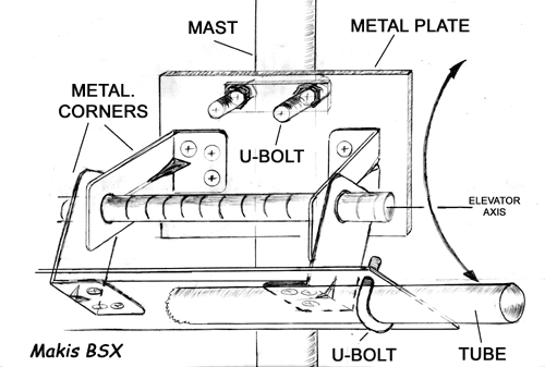
Prvé riešenie je na obrázku vyššie. Stačí ohnúť štyri platničky do L-ka, navŕtať niekoľko dier na skrutky a zohnúť pár U-čiek. V železiarstve sa dá kúpiť materiál za pár stoviek.
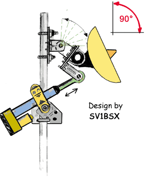
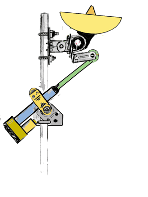
V tomto prevedení je vykonávateľom kruhového pohybu vodorovná tyč, ktorá tvorí záves. Pôsobením na pánt sa priamočiary pohyb aktuátora premieňa na kruhový. Konštrukcia musí byť bezpodmienečne masívna, inak dôjde pôsobením rôznych síl k deštrukcii. Celý anténny systém totiž pôsobí na záves, ktorý musí odolať aj najsilnejšiemu vetru. Výhodou je, ak sú antény malé a ľahké.
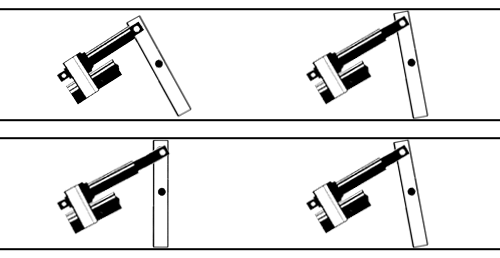
Nasledujúce obrázky ukazujú spôsob premeny priamočiareho pohybu na kruhový:
 |
 |
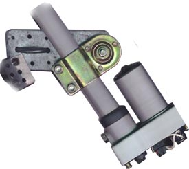
…. a obrázky nižšie zachytávajú prototyp elevačného systému s aktuátorom
 |
 |
 |
 |
Ďalšie riešenie zachytáva fotografia nižšie. S dvoma súosými trubkami sa GM4JJJ podarilo vytvoriť veľmi pevnú konštrukciu. Vonkajšia trubka je uchytená U-čkami na kovovú platničku. Vnútorná trubka je takého priemeru, aby akurát vošla do vonkajšej a dala sa otáčať bez drhnutia. Ak má dostatočnú dĺžku, celé uchytenie je veľmi stabilné a hodí sa aj pre rozmernejšie anténne systémy, napr.pre EME.

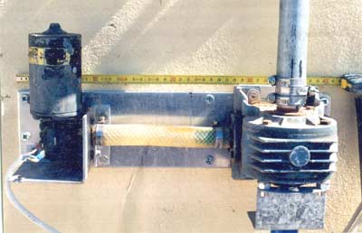
Na poslednom obrázku je jednoduchý home made rotátor SV1EPE využívajúci stieračové prevody. Pomer prevodu je 360:1, čiže aj maličký motorček zvládne otočiť stožiar bez problémov. Spojka medzi motorom a prevodovkou je zo záhradnej hadice!
Tak, a to by bolo všetko. Ak vás ešte niečo napadne, alebo máte poznámky a vylepšenia k uvedenému riešeniu, neváhajte a napíšte mi na sv1bsx@yahoo.gr . Ešte sa chcem zvlášť poďakovať mojej neteri Katerine Matiatos, ktorá mi pomohla s kompletizovaním tohto popisu.
Mak, SV1BSX https://www.qsl.net/sv1bsx/
