Autorom nasledujúceho zapojenia je Ole OZ2OE. Originálny popis v angličtine nájdete na http://hjem.get2net.dk/ole_nykjaer/oz2oe/hfpreamp/hfpreamp.html. Ďakujeme!
Predzosilňovač ku „hluchému“ KV prijímaču. Vhodný keď potrebujete extra citlivosť na 15, 12 a 10 m – napríklad kvôli satelitom.
V článku sa dočítate
Princíp
Tento jednoduchý malý predzosilňovač využíva výhodné vlastnosti monolitického zosilňovača MMIC MAR-6 od firmy MiniCircuits. Dosahuje zisk približne 20dB pri šumovom čísle 3dB v pásme 21 – 30 MHz. Selektivitu určuje pásmová priepusť na vstupe.
Mechanické vyhotovenie
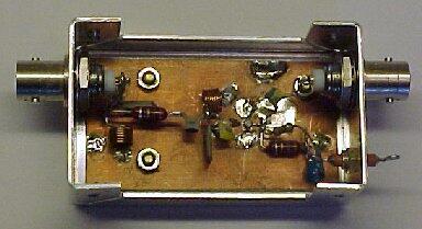
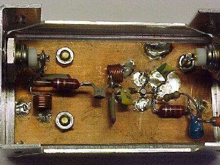
Predzosilňovač je skonštruovaný na obojstrannom plošnom spoji s rozmermi 32×60 mm. Medená plocha slúži ako zem a všetky súčiastky sú vo vzduchu. Plošný spoj je priskrutkovaný v malej kovovej skrinke zakončenej BNC konektormi.

Zapojenie
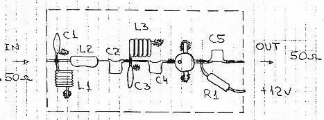
Schéma je nižšie. Vstup tvorí neladiteľná pásmová priepust z bežných súčiastok a dvoch vinutých cievok.
Pásmová priepust je navrhnutá na impedanciu 50 ohmov a výstupná impedancia je priamo v bode spojenia dvoch ladených obvodov.
Monolitický zosilňovač je napájaný z +12V cez zrážací rezistor 560 ohmov. Výstup je širokopásmový.

L1, L3: 6,5 závitu medeným drôtom s priemerom 0,5mm na priemere 4,5 mm
L2: 1,5 uH RFC
Osadenie
Súčiastky sú osadené tak, ako to znázorňuje obrázok. Vstup je vľavo.

(Na obrázku sú aj dve súčiastky, ktoré na schéme nenájdete. Sú to 4,7uH RFC a 3,3uF, ktoré sa používajú podľa katalógového zapojenia v napájaní. Akokoľvek – 560 ohmový rezistor funguje výborne, ale na plošnom spoji ostala stále pripojená tlmivka.)

Naladenie
Nie je potrebné. Zosilňovač je širokopásmový. Iba som odmeral spotrebu prúdu – 16 mA je v poriadku.
Vlastnosti
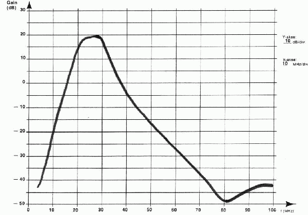
Vlastnosti tohto predzosilňovača určujú hlavne vlastnosti monolitického zosilňovača. Katalógový údaj MAR-6 hovorí o šumovom čísle 3 dB a IP 3.rádu +14,5 dBm. Pásmová priepust znižuje celkový zisk ako je možné vidieť na obrázku.

Je veľmi dôležité, že zisk výrazne poklesne pri nižších frekvenciách, ináč by silné signály z frekvencií pod 15 MHz mohli preniknúť do zosilňovača a na nelinearitách vytvoriť rušivé produkty v pásmach 21 – 30 MHz.
Pásmová priepusť má na nižších frekvenciách mierne zvlnenie.
Možné zmeny
Predzosilňovač môže byť osadený aj iným monolitickým obvodom. Pre predzosilňovače sú vhodné so stredným ziskom (15 – 25 dB), nízkym šumom a IP 3.rádu najmenej +10 dBm. Dajte pozor na odlišné puzdrá a rozmiestnenie vývodov.
