Predchádzajúci článok opisoval ako pomocou jednoduchého obvodu možno aj starší TCVR použiť na prevádzku s digimódmi. Podobné zapojenie sa dá použiť aj na kľúčovanie CW z počítača. Obvod som úspešne vyskúšal v pretekoch a môžem s istotou povedať, že je skvelým pomocníkom počas (niekedy často) vypätých chvíľ, ktoré kontestovanie prináša. Vtedy sa totiž ráta každá ušetrená sekunda. HAM programy už dlho dokážu vyslať text volacej značky prijatej stanice, tak prečo to nevyužiť?

Upozorňujem, že opísané riešenie využíva VOX na spustenie kľúčovania, neobsahuje teda PTT obvod.
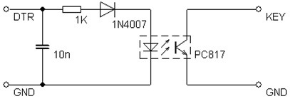
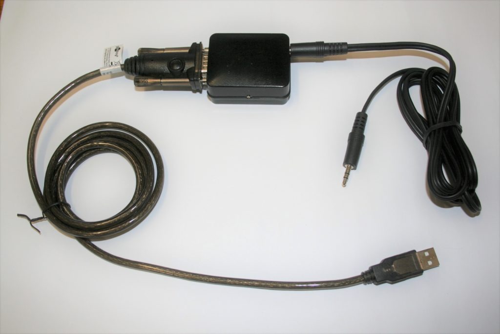
Kto by doma nenašiel optočlen PC817, môže použiť s výhodou jeho náhrady: 4N35, 4N36, 4N37, 4N25, 4N26, 4N28, PC816, PC817, 4N27, 4N36 a série H11Ax. Obvod využíva prevodník USB na RS232 od výrobcu Prolific, tomu bola prispôsobená hodnota odporu 1 kΩ. Dôvod bol celkom prozaický – mal som akurát taký k dispozícii. Áno, čipy od daného výrobcu sa neodporúčajú požívať na tento účel, no ja som zatiaľ nezaznamenal žiadny problém. Kto by chcel prevodník vynechať, môže siahnuť po riešení s obvodom FT232RL, ako HB9AMO opisuje na svojej stránke: http://www.hb9amo.net/ts50.php. Technicky vzaté, ide v podstate len o zmenu hodnoty rezistora. Signály DTR a GND na schéme vľavo privádzame na vstup prevodníka a signály KEY a GND na vstup TCVR cez stereo jack. Na špičku jacku pripojíme KEY a na koncový prstenec GND, pričom stredný prstenec necháme nezapojený.
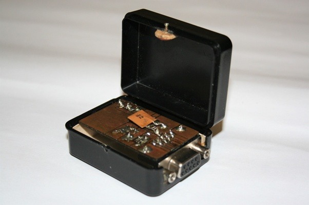
Je vidno, že za nepatrné náklady sa dá CW prevádzka obohatiť, uľahčiť a spríjemniť. Moje riešenie je umiestnené v malej krabičke, z ktorej trčia konektory jack a RS232. Pri použití obvodu FT232RL stačí elektroniku „zababúšiť“ do zmršťovacej bužírky, čím vznikne kábel vhodný aj na portable.

Bonus 1: Ovládanie cez program Atalanta Locator
Ak ste sa dočítali až sem a požívate klasický a stále obľúbený program Atalanta Locator, dám vám jeden tip. Tomáš, OM5AST poskytuje užitočný návod ako spustiť Locator aj pod Windows 10: https://github.com/tomasgeci/atalanta-locator-dosbox Kto by k tomu chcel ešte ovládať CW cez Lokator, spraví nasledovné:
- V priečinku so súbormi programu Locator otvoriť súbor LOCATOR.INI a v časti [CW] nastaviť ENABLE_PTT=0
- Na konci súboru dosbox-0.74.conf pridáme riadok serial1=directserial realport:com1 Kde com1 je názov skutočného portu počítača, kde máme pripojený kľúčovací obvod
- Program spustíme podľa priloženého návodu
Bonus 2: Ovládanie cez program N1MM
Nasledujúci postup platí pre zvolený jazyk angličtinu:
- Z hornej ponuky zvoliť Configure
- Potom vybrať položku Configure Ports, Mode Control, Audio, Other …
- Ponechať záložku Hardware
- V stĺpci Port vybrať port, kde je pripojený kľúčovací obvod
- V stĺpci Radio nechať None
- Zaškrtnúť CW/Other
- V Details kliknúť na tlačidlo Set
- Vybrať DTR pre CW, RTS nastaviť na Always Off
Poznámka: Je možné vybrať aj signál RTS pre CW, ale ten sa spravidla používa pre PTT.
Martin Jánoš, OM1MJ
